Eccentric planar fluorescent tube

a fluorescent tube, eccentric technology, applied in the direction of discharge tube luminescnet screen, coupling device connection, lighting and heating apparatus, etc., can solve the problem of application limit, and achieve the effect of widening the application rang

Inactive Publication Date: 2007-08-14
YU WILLIAM
View PDF13 Cites 4 Cited by
  • Summary
  • Abstract
  • Description
  • Claims
  • Application Information

AI Technical Summary

Benefits of technology

[0008]The invention is directed to the problems described above, and intended to provide a novel eccentric planar fluorescent tube with more compact design, higher luminous flux and expanded application range.
[0011]In the eccentric planar fluorescent tube (EPFT) resulted from above configuration, as compared to the prior planar fluorescent tube, the luminous flux is improved, and can be inserted into the center-pole configured lamp fixtures in radial direction to the center-pole, thus widening the application range.

Problems solved by technology

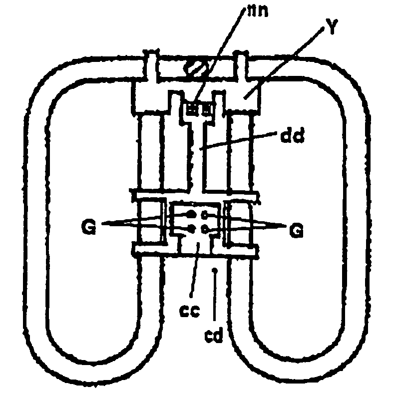
1. Although they are used in ceiling mount, surface mount and recessed fixtures in general, they can not be used in center-pole configured fixture since they can not get through and attached to the center-pole due to their leg member arranged at the center of the tube plane or on the close periphery section of tube, and thus leads limitation in their applications.

Method used


Image

  • Eccentric planar fluorescent tube
  • Eccentric planar fluorescent tube
  • Eccentric planar fluorescent tube

Examples


Embodiment Construction

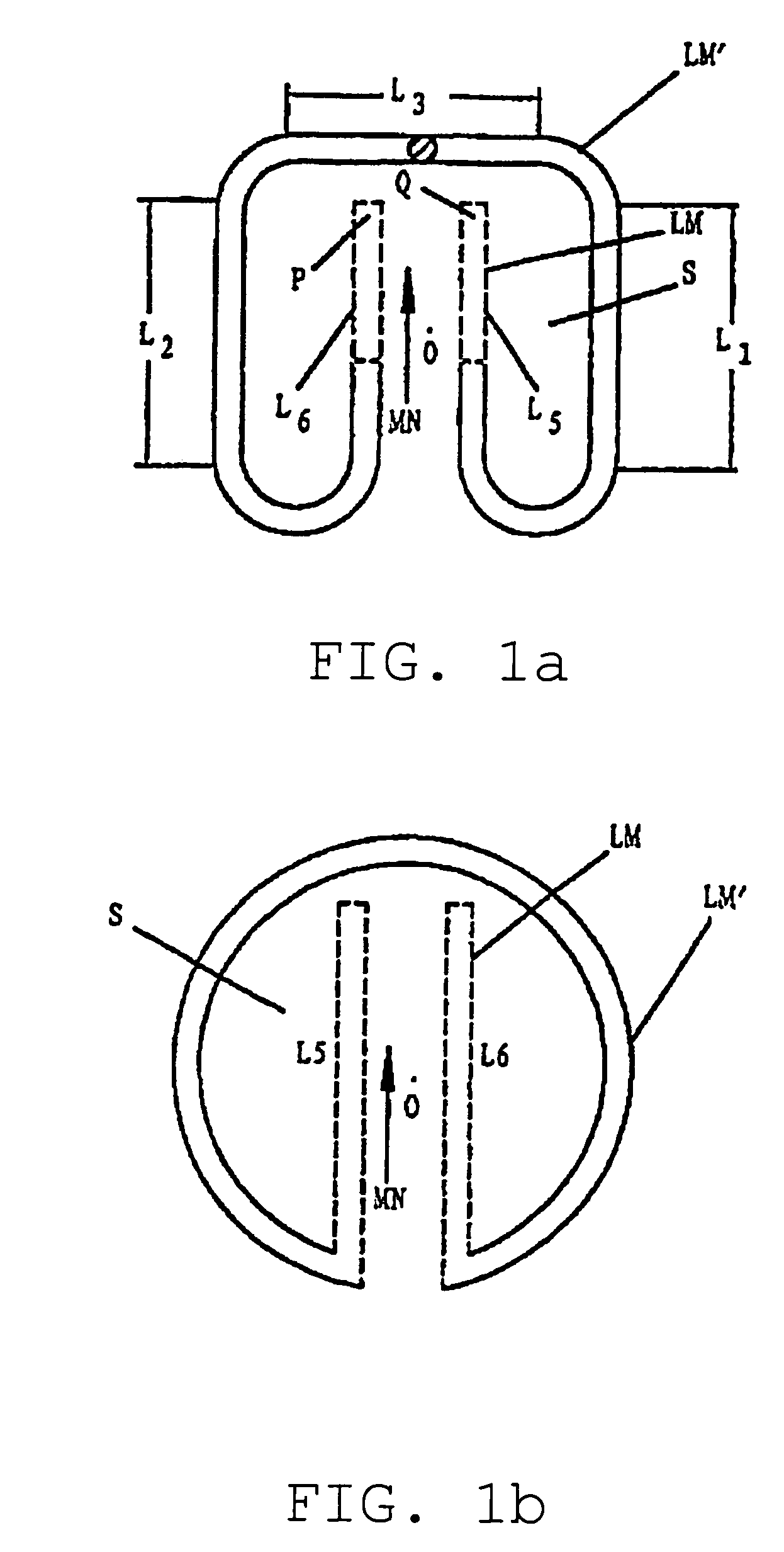
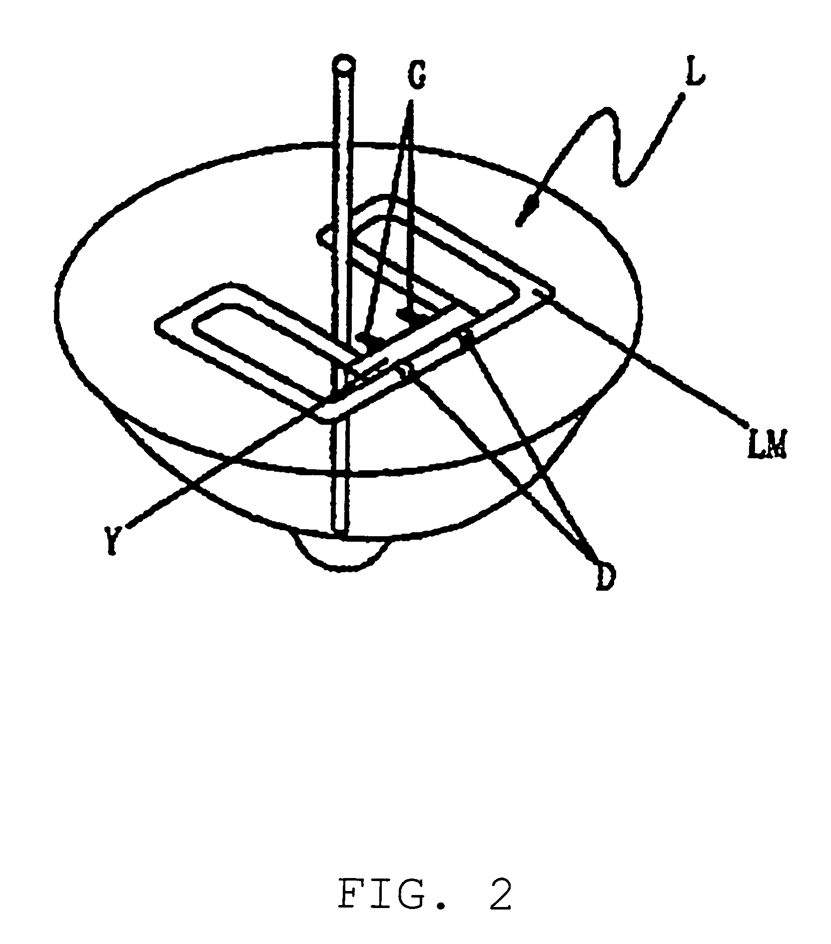
[0016]Referring to FIGS. 1(a) and 1(b), F1(a) shows a 2D tube, and FIG. 1(b) shows a circle tube. The tube section LM′ of planar fluorescent tube (PFT) in prior art is indicated by solid line, while the tube section LM of EPFT (L) in accordance with the invention (see FIG. 2 for overall structure) is indicated by dotted line in addition to the solid line, as shown in FIGS. 1(a) and 1(b). As can be seen from FIGS. 1(a), 1(b) and FIG. 2, the EPFT (L) of the invention comprises a planar tube section LM, two tube-ends P and Q for drawing out filaments, and a leg member Y set between two tube-ends P and Q. The improved structure of EPFT (L) in accordance with the invention lies in that two tube-ends P and Q are extended based on the prior PFT, from one periphery side of tube section LM (lower side as shown in FIGS. 1(a) and 1(b)) to another periphery side opposed to said one periphery side (upper side as shown in FIGS. 1(a) and 1(b)) within the tube section LM surrounding plane S to obta...


PUM


Abstract

An eccentric planar fluorescent tube includes an outer planar fluorescent tubular member that extends substantially but not completely about a center point and which is extended by two inner portions that extend from a first peripheral portion of the outer tubular member and on opposite sides of the center point and terminate at ends proximate to an opposite peripheral portion of the outer tubular member and wherein the ends are connected by a leg member for supplying power to the fluorescent tube. In one embodiment, the leg member includes electrical contacts that extend substantially in a plane of the outer tubular member and, in another embodiment, a central adapter may be provided including electrical contacts that extend transversely with respect to the plane of the outer tubular member.

Description

BACKGROUND OF THE INVENTION[0001]1. Field of Invention[0002]The invention relates to a plane-type fluorescent tube and more particularly, to an eccentric planar fluorescent tube.[0003]2. Description of Related Art[0004]Nowadays, the plane-type fluorescent lamps such as 2D, circular and polygonal fluorescent lamps are available popularly in the market with their tube typically in planar shape and leg member used as power supplying means located at the center of tube plane (e.g. 2D tube) or on the close periphery section of tube (e.g. circular and polygonal tubes).[0005]The shortcomings of these plane-type fluorescent tubes are as follows.[0006]1. Although they are used in ceiling mount, surface mount and recessed fixtures in general, they can not be used in center-pole configured fixture since they can not get through and attached to the center-pole due to their leg member arranged at the center of the tube plane or on the close periphery section of tube, and thus leads limitation in...

Claims


Application Information

Patent Timeline
Patent Type & Authority Patents(United States)
IPC IPC(8): H01J63/04F21V7/10H01J5/48H01J5/50H01J5/54H01R33/08H01J61/30H01J61/32
CPCH01J61/30H01J61/327
Inventor YU, WILLIAM
Owner YU WILLIAM
Why Eureka
Try Eureka