Method for moving object detection using an image sensor and structured light

a technology of image sensor and structured light, applied in image enhancement, instruments, individual entry/exit registers, etc., can solve the problems of not being able to directly determine, unauthorized persons may bypass validation security, and systems not well suited to certain security systems

Inactive Publication Date: 2013-02-14
NICHANI SANJAY +1
View PDF7 Cites 58 Cited by
  • Summary
  • Abstract
  • Description
  • Claims
  • Application Information

AI Technical Summary

Benefits of technology

[0010]A factory calibrated camera and laser combination system is used to compute 3-dimensional (3D) coordinates of laser points that are visible in a field of view. During installation, a plane of known height parallel the ground is calibrated relative to a camera. This is referred to as a world plane or coordinate system. Only those points are considered interesting that fall within a target volume relative to this plane. This volume may be static; e.g., all points which are 5 inches above the ground in a hallway, or the volume may be dynamically created, e.g. points inside the two wings of a moving revolving door. These points of interest are then used to create a line or row in a depth (also called height) image. This image is concatenated over time in the form of consecutive rows. Optionally, and in addition, a trajectory is computed at these points of interest to create a line or row in a veloci...

Problems solved by technology

A typical security issue associated with most access controlled portal security systems is that when one person obtains valid access; an unauthorized person may bypass the validation security by “piggybacking” or “tailgating”.
Tailgating occurs when an authorized person knowingly or unknowingly provides unauthorized access through a portal to another person traveling in the opposite direction.
But, such systems are not well suited for certain security systems because they are easily circumvented; only detect a certain class of objects moving through a narrowly constrained space; and cannot directly determine an object's direction or velocity.
The sensors also often have problems maintaining uniform sen...

Method used


Image

  • Method for moving object detection using an image sensor and structured light
  • Method for moving object detection using an image sensor and structured light
  • Method for moving object detection using an image sensor and structured light

Examples


Embodiment Construction

[0032]A description of the preferred embodiments of the invention is described below:

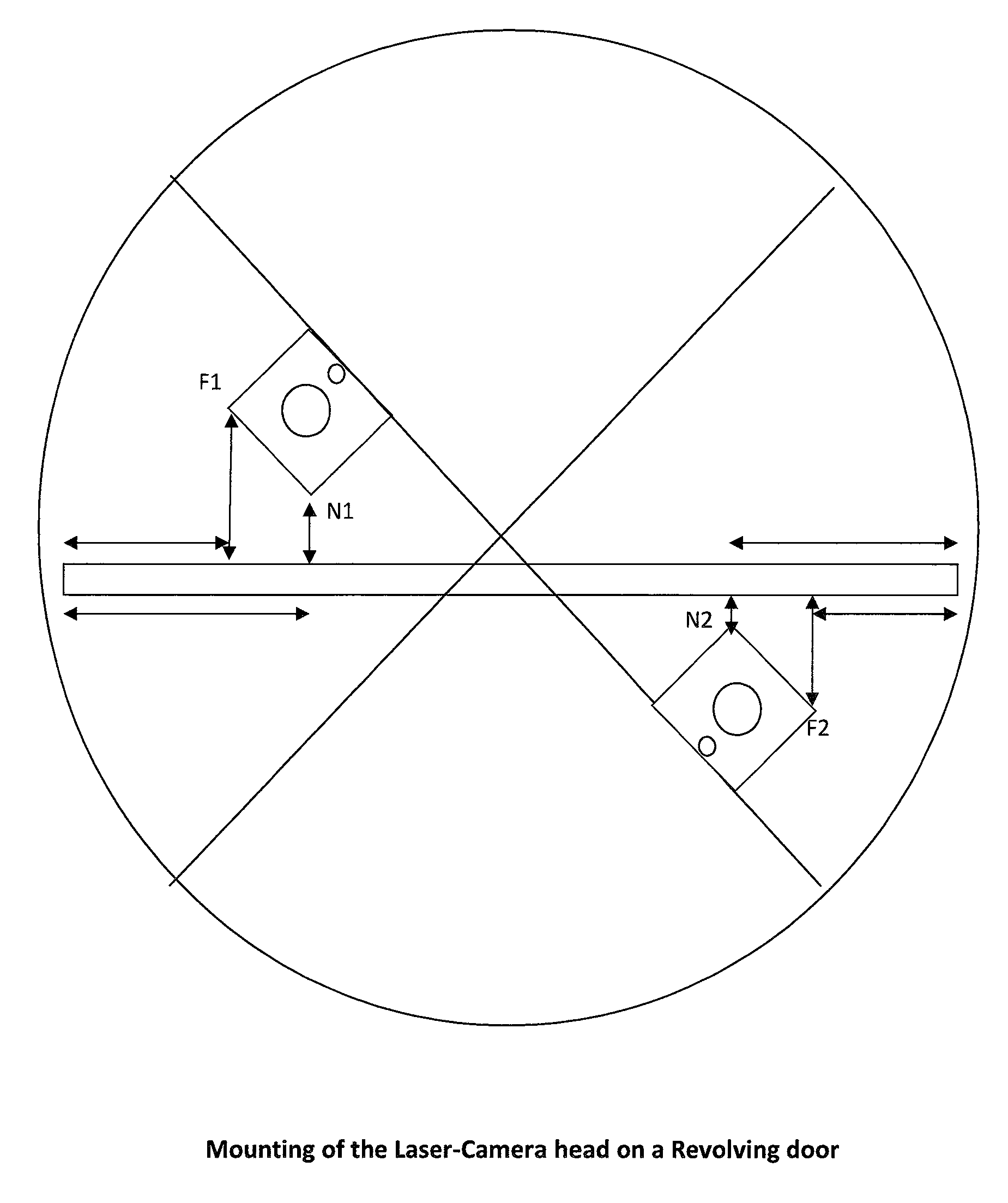
[0033]The present invention is directed at systems and methods of providing enhanced portal security through the use of a camera and a structured light. A particular embodiment is APATS-R that detects and optionally prevents access violations, such as piggybacking and tailgating. APATS-R generates a three-dimensional image of the portal scene from a camera and a structured light source, and further detects and tracks people moving through the resulting target volume.

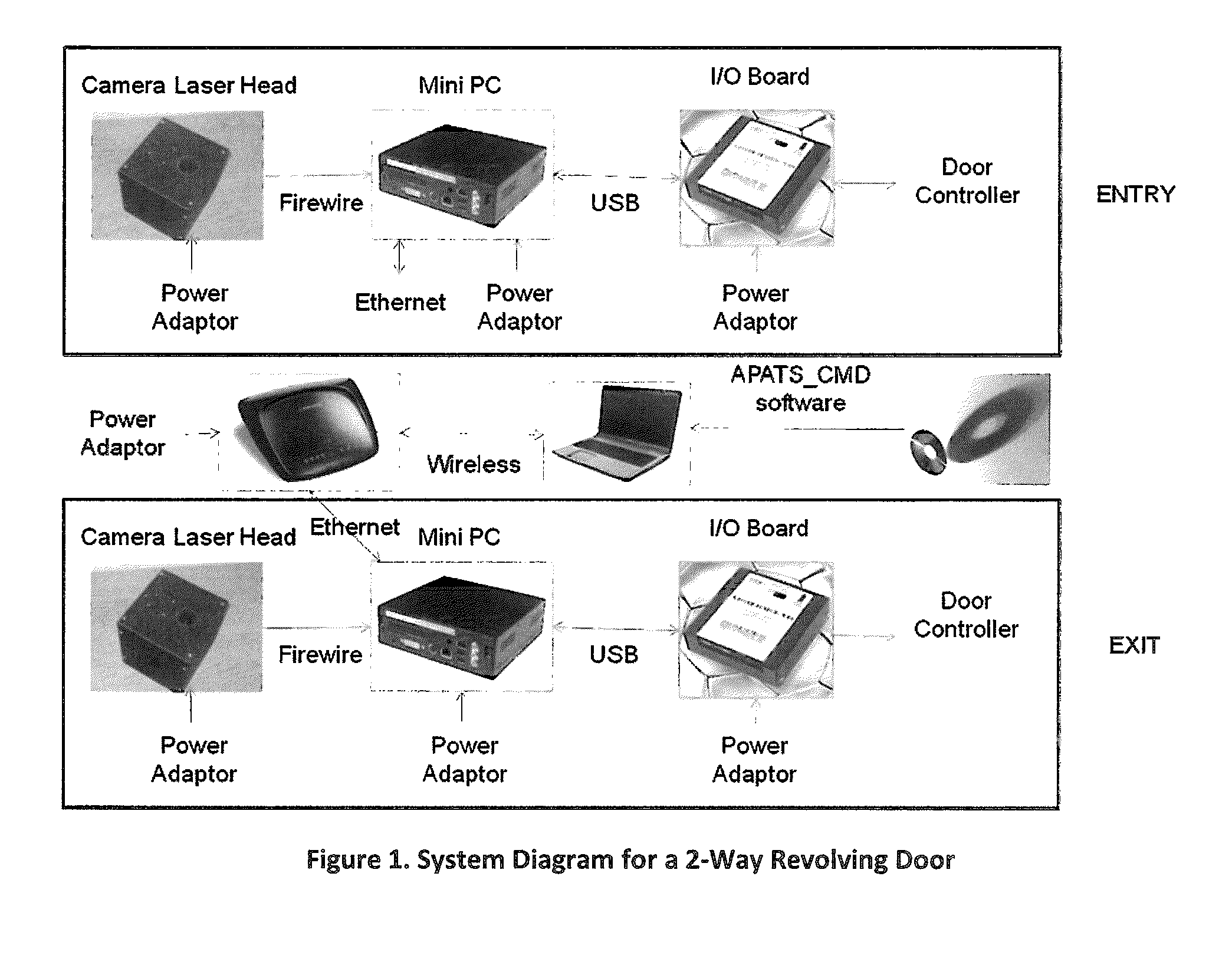
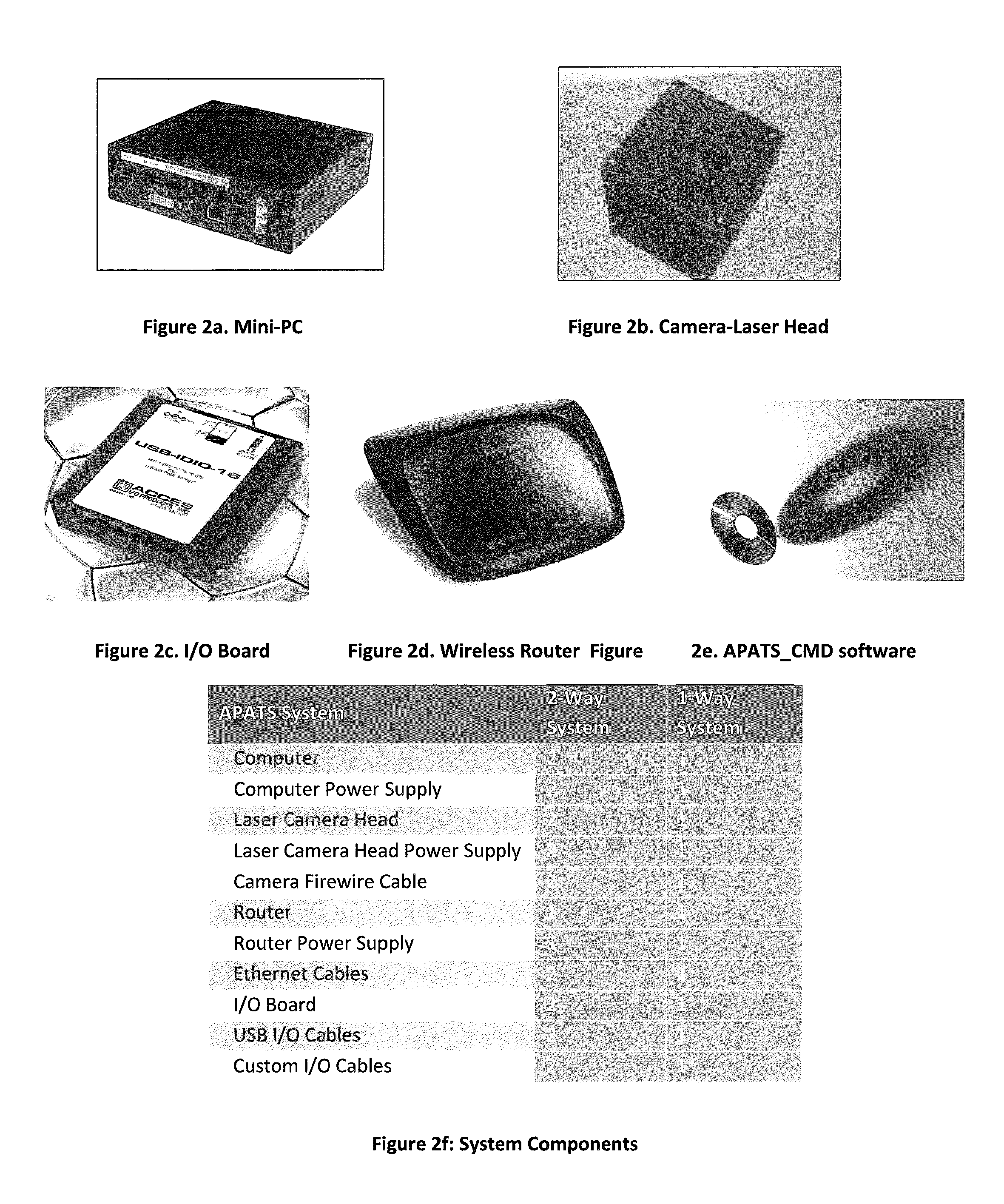
[0034]The APATS-R system consists of the following components as shown in FIG. 1 and FIG. 2.[0035]Small form factor mini-PC with mounting brackets[0036]Camera-laser head mounted over-head[0037]I / O interface box from the PC to door controller (DC)[0038]Router for wireless access to the PC[0039]Setup software APATS_CMD for installation on a setup laptop[0040]Firewire cable to connect camera-laser head to the mini-PC.[0041]Power adapter for...


PUM


Abstract

A method for detecting moving objects including people. Enhanced monitoring, safety and security is provided through the use of a monocular camera and a structured light source, by trajectory computation, velocity computation, or counting of people and other objects passing through a laser plane arranged perpendicular to the ground, and which can be setup anywhere near a portal, a hallway or other open area. Enhanced security is provided for portals such as revolving doors, mantraps, swing doors, sliding doors, etc., using the monocular camera and structured light source to detect and, optionally, prevent access violations such as “piggybacking” and “tailgating”.

Description

CROSS-REFERENCE TO RELATED APPLICATIONS[0001]This application claims the benefit of U.S. provisional patent application 61 / 328,518 filed Apr. 27, 2010, the disclosure of which is incorporated herein by reference.STATEMENT REGARDING FEDERALLY SPONSORED RESEARCH[0002]Not Applicable.BACKGROUND OF THE INVENTION[0003]The movement of people or objects through various spaces, passageways and portals is monitored or controlled for any number of purposes including safety, security or traffic monitoring. Such monitoring and control are performed most efficiently when it is done automatically and with little or no human intervention.[0004]Automated and manual security portals provide controlled access to restricted areas and are used for keeping track of when (and which) individuals are inside or outside a facility. These security portals are usually equipped with card access systems, biometric access systems or other systems for validating a person's authorization to enter restricted areas or...

Claims


Application Information

Patent Timeline
IPC IPC(8): H04N13/02G06V10/145
CPCG06T7/20G07C9/00G06K9/00369G06T2207/30242G06T7/0057G06T2207/30232G06T2207/30241G06K9/00778G06T7/521G06V40/103G06V20/53G06V10/145
Inventor NICHANI, SANJAYREDDY, CHETHAN
Owner NICHANI SANJAY
Why Eureka
Try Eureka