Multilayer capacitor

a capacitor and multi-layer technology, applied in the direction of capacitors, fixed capacitor details, electrical equipment, etc., can solve the problems of mechanical distortion, namely, electrostriction, increase manufacturing cost or complicating manufacturing processes, and it is difficult to enhance the performance of the capacitor itself using various other materials, so as to reduce electrostriction vibration, suppress electrostriction vibration, and improve the effect of capacitor performan

Active Publication Date: 2013-02-14
TDK CORPARATION
View PDF0 Cites 48 Cited by
  • Summary
  • Abstract
  • Description
  • Claims
  • Application Information

AI Technical Summary

Benefits of technology

The patent text discusses the issue of electrostrictive vibration in multilayer capacitors made with ferroelectric ceramic materials. The text explains that this vibration can be prevented through a material approach, but this approach restricts the materials used to form the capacitor, making it difficult to improve its performance using different materials. The technical effect of the patent text is to provide a solution to prevent electrostrictive vibration in multilayer capacitors without restricting the materials used.

Problems solved by technology

When an electric field is applied to such ferroelectric ceramic material, mechanical distortion, namely, electrostriction, occurs in the material.
However, when adopting the method of making a certain separation between the board and the capacitor's main body using the electrode connection parts, such addition of the electrode connection parts may increase the manufacturing cost or complicate the manufacturing processes, so further improvement is required.
However, such material approach would restrict the materials applied to constitute the multilayer capacitor, thereby making it difficult to enhance the performance of the capacitor itself using various other materials.
However, having a configuration including a third internal electrode, as described above, is unavoidable, and this would be a structural constraint.
Due to such structural constraint, the structural approach does not work effectively to suppress electrostrictive vibration of multilayer capacitors having general-purpose structures.

Method used


Image

  • Multilayer capacitor
  • Multilayer capacitor
  • Multilayer capacitor

Examples


Embodiment Construction

[0054]Embodiments of the invention will be described below with reference to the attached drawings. In the drawings, in order to facilitate understanding of the description, the same components are given the same reference numerals wherever possible, and repetitive descriptions will be omitted.

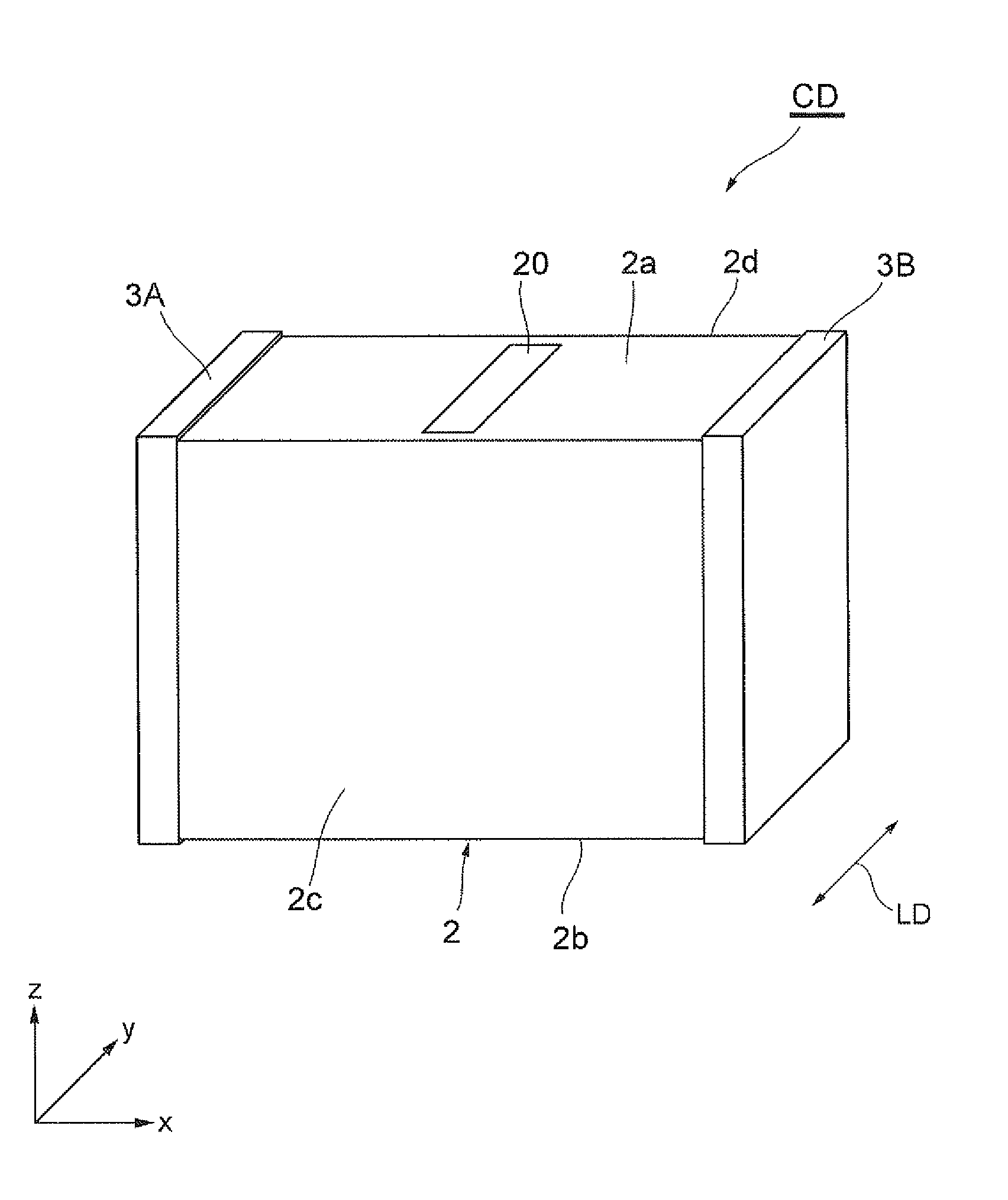
[0055]Referring to FIG. 1, a multilayer capacitor according to a first embodiment of the invention will be described. FIG. 1 is a perspective view schematically illustrating the appearance of a multilayer capacitor CD according to the first embodiment of the invention.

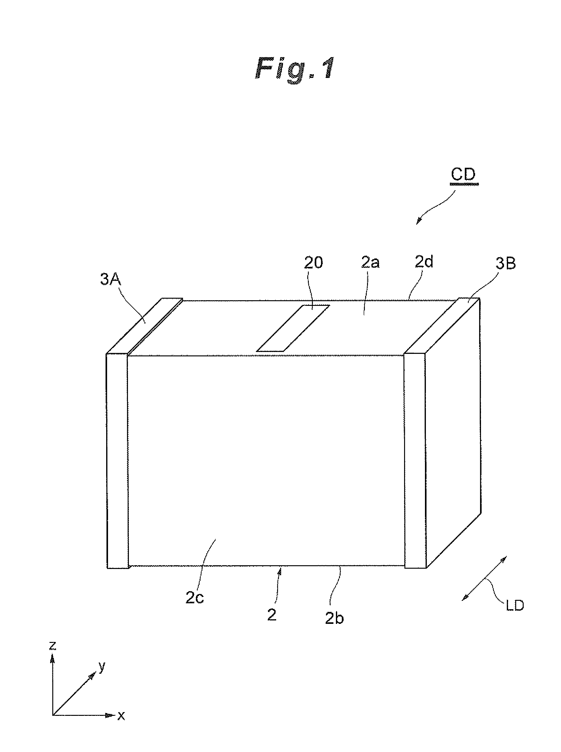
[0056]The multilayer capacitor CD has a multilayer body 2 and a pair of terminal electrodes 3A and 3B. The multilayer body 2 is in an approximately rectangular parallelepiped shape and has a first principal surface 2a, a second principal surface 2b, a first side face 2c, a second side face 2d, a first end face 2e (not specified in FIG. 1) and a second end face 2f (not specified in FIG. 1).

[0057]The second principal surface 2b is ...


PUM


Abstract

A multilayer capacitor that can suppress electrostrictive vibration without material constraint and with applicability to various structures, including general-purpose structures. A multilayer capacitor has: an element body formed of dielectric ceramic; and a plurality of internal electrodes disposed inside the element body such that the internal electrodes are stacked with ceramic layers sandwiched therebetween. The multilayer capacitor is provided with a capacitor area which includes the plurality of internal electrodes and a first suppression area and a second suppression area for reducing electrostriction caused by the plurality of internal electrodes so as to suppress noise. The first suppression area is adjacent to the capacitor area and the thickness of the second suppression area is determined according to the arrangement of the plurality of internal electrodes.

Description

CROSS-REFERENCES TO RELATED APPLICATIONS[0001]The present application relates to and claims priority from Japanese Patent Application No. 2011-175133, filed on Aug. 11, 2011, the entire disclosure of which is incorporated herein by reference.BACKGROUND[0002]1. Field of the Invention[0003]The present invention relates to a multilayer capacitor.[0004]2. Description of Related Art[0005]Multilayer capacitors are one example of multilayer electronic components and are widely used as electronic components having small sizes, high capacity and high reliability. Electric and electronic devices have a large number of multilayer capacitors used therein. As devices have been becoming smaller in size and achieving higher performance in recent years, further improvement of multilayer capacitors in terms of small size, high capacity, low cost and high reliability is even more strongly demanded.[0006]Ferroelectric ceramic material is typically used for currently available small-size and high-capac...

Claims


Application Information

Patent Timeline
Patent Type & Authority Applications(United States)
IPC IPC(8): H01G4/30
CPCH01G4/30H01G4/015H01G2/24H01G2/22
Inventor TOGASHI, MASAAKI
Owner TDK CORPARATION
Why Eureka
Try Eureka