Gas laser apparatus equipped with power calculation unit

a technology of power calculation and laser equipment, which is applied in the direction of electrical equipment, laser details, active medium materials, etc., can solve the problems of difficult accurate measurement, inconvenient measurement of the overall power consumption of the gas laser apparatus, and expensive and laborious methods, etc., and achieve the effect of accurately and easily measured

Active Publication Date: 2013-02-14
FANUC LTD
View PDF2 Cites 9 Cited by
  • Summary
  • Abstract
  • Description
  • Claims
  • Application Information

AI Technical Summary

Benefits of technology

[0012]In view of the above problems, it is an object of the present invention to provide a gas ...

Problems solved by technology

As described above, one possible method for measuring the power consumption of a gas laser apparatus is to install a power meter, but this method is costly and laborious.
On the other hand, if the technique disclosed in above-cited Japanese Unexamined Patent Publication No. 2010-115063 is applied to calculate the power consumption of a gas laser apparatus, it may be possible to calculate the power consumption of the blower motor by suitably combining the motor current detection unit and the motor rotational speed detection unit, but when measuring the power consumption of the gas laser apparatus, it is difficult to accurately measure it because the discharge loa...

Method used


Image

  • Gas laser apparatus equipped with power calculation unit
  • Gas laser apparatus equipped with power calculation unit
  • Gas laser apparatus equipped with power calculation unit

Examples


Embodiment Construction

[0022]A gas laser apparatus equipped with a power calculation unit will be described below with reference to the drawings. It should, however, be understood that the present invention is not limited to the accompanying drawings, nor is it limited to the particular embodiment described herein.

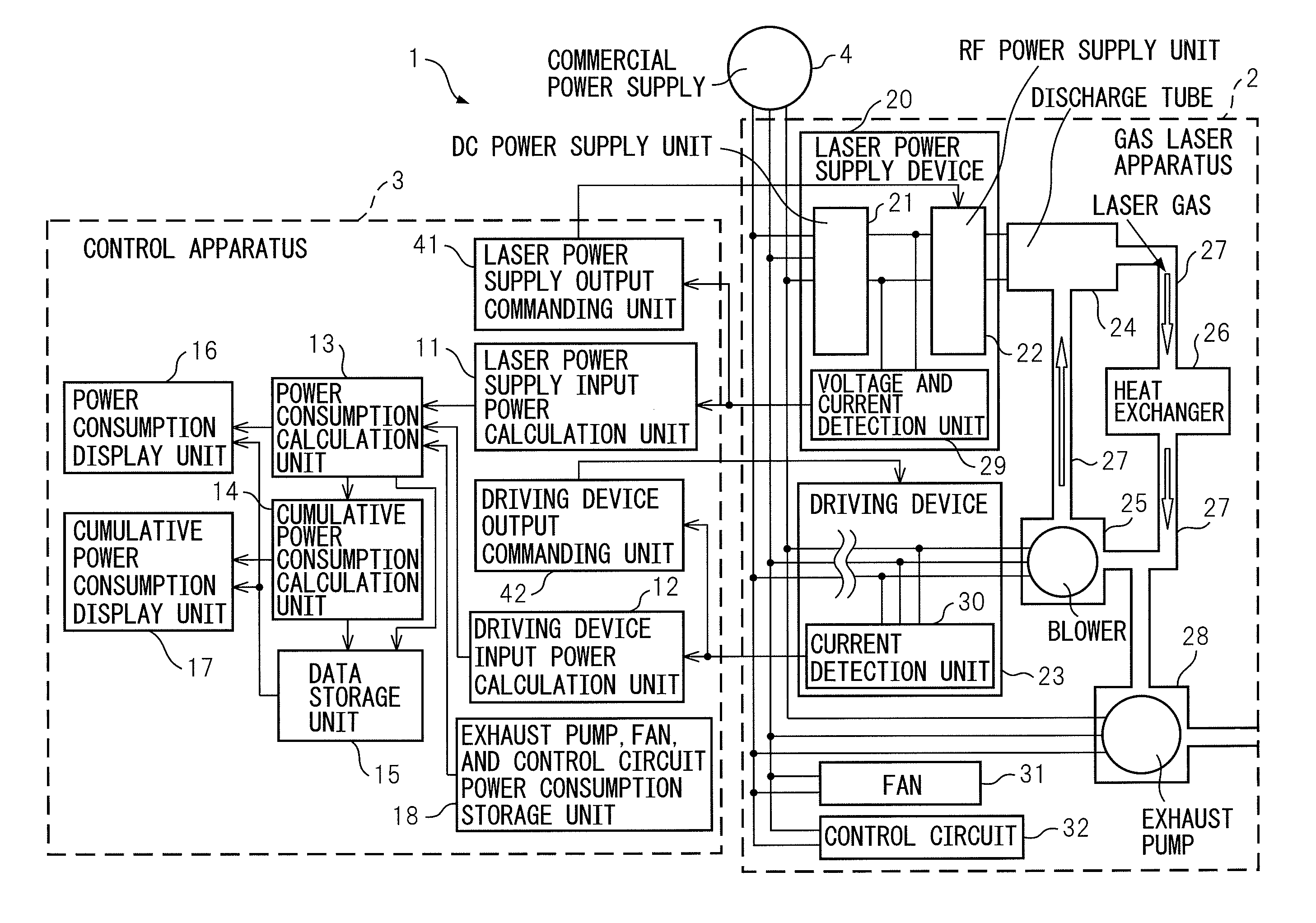
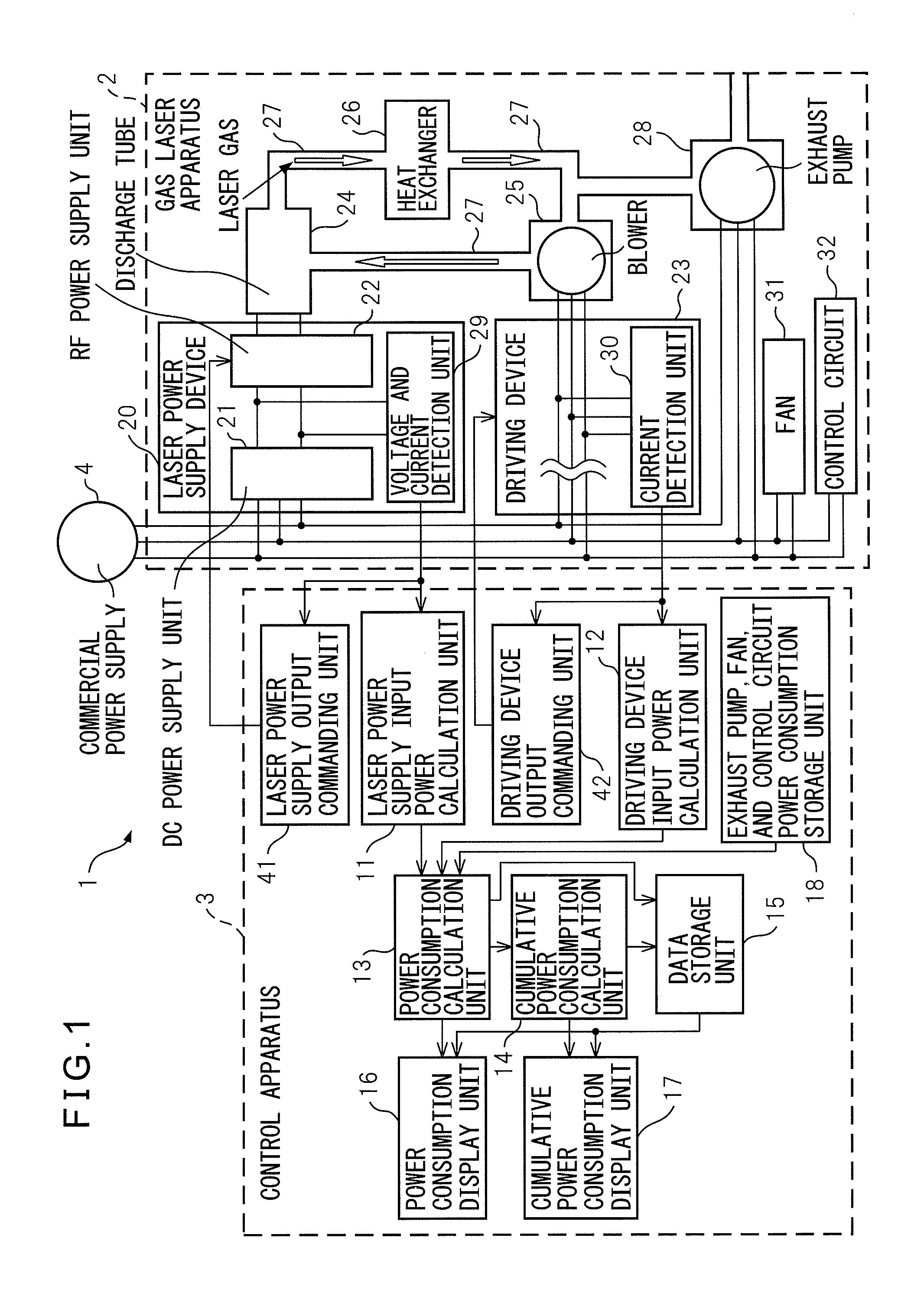
[0023]FIG. 1 is a block diagram showing the gas laser apparatus according to the embodiment of the present invention. The gas laser apparatus 1 according to the embodiment of the present invention includes, in addition to the gas laser apparatus proper 2, a control apparatus 3 which controls the overall operation of the gas laser apparatus 2.

[0024]The gas laser apparatus proper 2 includes a discharge tube 24, a laser power supply device 20 which generates a radio-frequency voltage for exciting a laser gas in the discharge tube 24 by producing an electric discharge therein, a blower 25 for supplying the laser gas into the discharge tube 24, a driving device 23 for driving the blower 25, a heat ex...


PUM


Abstract

Disclosed is a gas laser apparatus having: a first estimation unit which calculates an estimate of input power to the laser power supply device by using the output current value and output voltage value of the DC power supply unit and also using the efficiency of conversion from input power to output power by the DC power supply unit; a second estimation unit which calculates an estimate of input power to the driving device by using the output current value of the driving device; and a power calculation unit which calculates the power consumption value of the gas laser apparatus, based on the estimate of the input power to the laser power supply device and the estimate of the input power to the driving device.

Description

BACKGROUND OF THE INVENTION[0001]1. Field of the Invention[0002]The present invention relates to a gas laser apparatus having a laser power supply device for exciting a laser gas in a discharge tube by producing an electric discharge therein and a blower for supplying a laser gas into the discharge tube, and more particularly to a gas laser apparatus equipped with a power calculation unit for calculating power consumed during operation.[0003]2. Description of the Related Art[0004]Today, there is an increasing need to reduce energy consumption in various technical fields. The field of gas laser apparatus is no exception, and the need to reduce power consumption during operation as much as possible has also been increasing in this field. In a gas laser apparatus, a laser gas is supplied into a discharge tube, and laser light is produced by exciting the laser gas in an electric discharge produced by applying a radio-frequency voltage between the electrodes inside the discharge tube. Fo...

Claims


Application Information

Patent Timeline
IPC IPC(8): H01S3/22
CPCH01S3/104H01S3/036H01S3/0014H01S3/041
Inventor KAGIWADA, SATOSHIKUBO, YOSHITAKA
Owner FANUC LTD
Why Eureka
Try Eureka