Method and apparatus for improving throughput of a modem

a modem and throughput technology, applied in the field of improving throughput, can solve the problems of difficult management and monitoring of complex networks, high cost, and inconvenience of voice or data traffic, and achieve the effects of improving network element throughput, improving data speed, and improving network efficiency

Inactive Publication Date: 2013-02-14
GENERAL INSTR CORP
View PDF3 Cites 9 Cited by
  • Summary
  • Abstract
  • Description
  • Claims
  • Application Information

AI Technical Summary

Benefits of technology

[0016]The system preferably allows an operator to automatically configure the CMTS to best align the network elements with the available logical channels. The invention provides a cost effective manner for improving network element throughput, providing higher data speeds to subscribers. The total network throughput may also be increased in addition to individual subscriber throughput because each network element will be running at its best possible modulation mode and it should not bring other modems down (to a lower bandwith) with it. All the modems that can only run in QPSK will be on the QPSK channel, the modems that can run at 16QAM will be on the 16QAM channel and so on. The invention may be done in real time so there are no operator configuration changes or intervention where they could make a mistake and assign a network element to the wrong channel. Another advantage is that there is no or little dollar cost to cable operators to get better throughput.

Problems solved by technology

The extensive and complex networks are often difficult for a cable operator to manage and monitor.
Any disruption of voice or data traffic is a great inconvenience and often unacceptable to a subscriber.
Many still in use are only capable of running error free at the QPSK modulation mode.
In doing this the modems that are capable of passing data error free at higher modulation modes (and higher throughput) are penalized and do not achieve their potential throughput.
While the approach may work well under ideal conditions, many modems do not handle those protocols properly.
If the modems fail to move with those protocols then they may possibly deregister causing loss of service for subscribers.

Method used


Image

  • Method and apparatus for improving throughput of a modem
  • Method and apparatus for improving throughput of a modem
  • Method and apparatus for improving throughput of a modem

Examples


Embodiment Construction

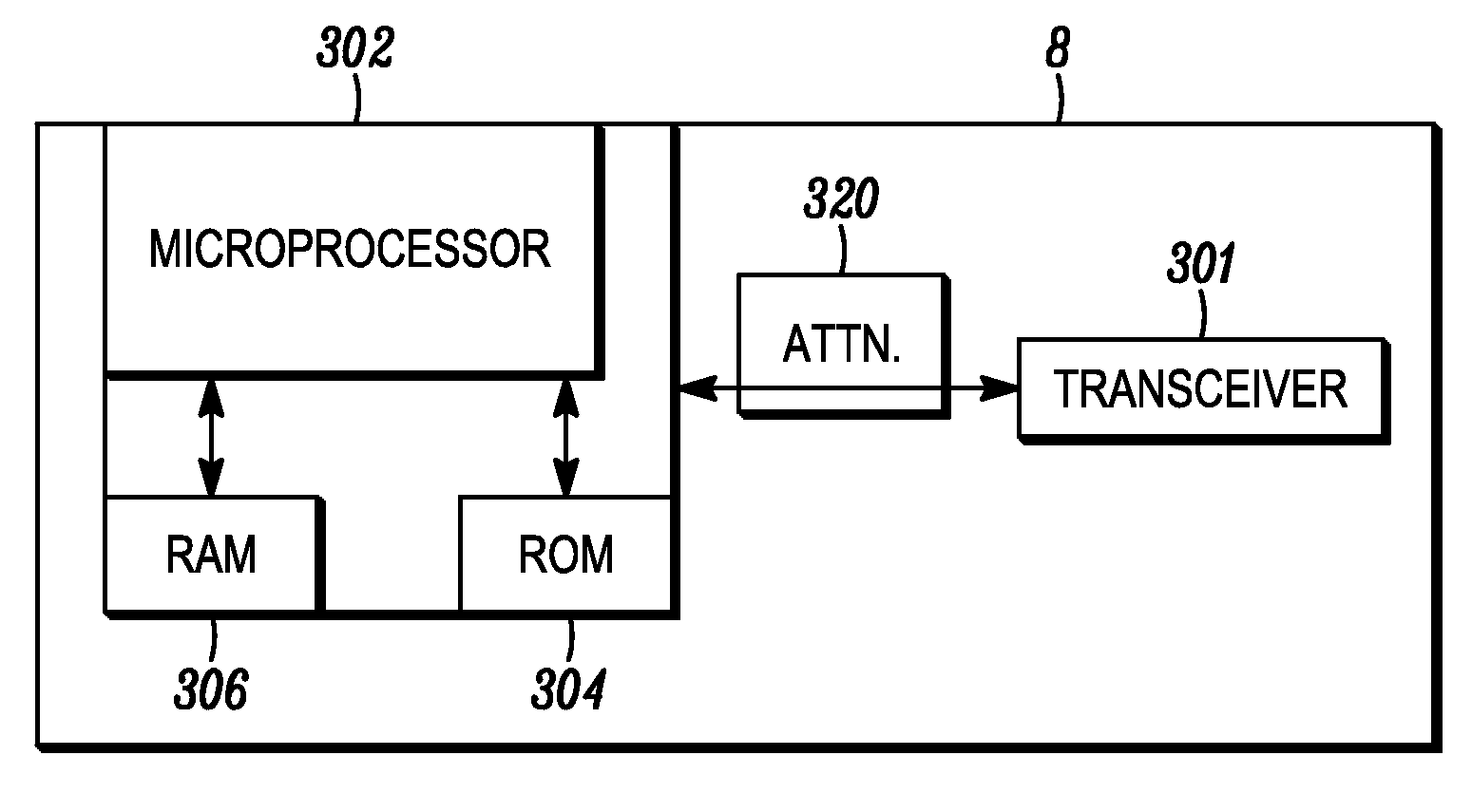
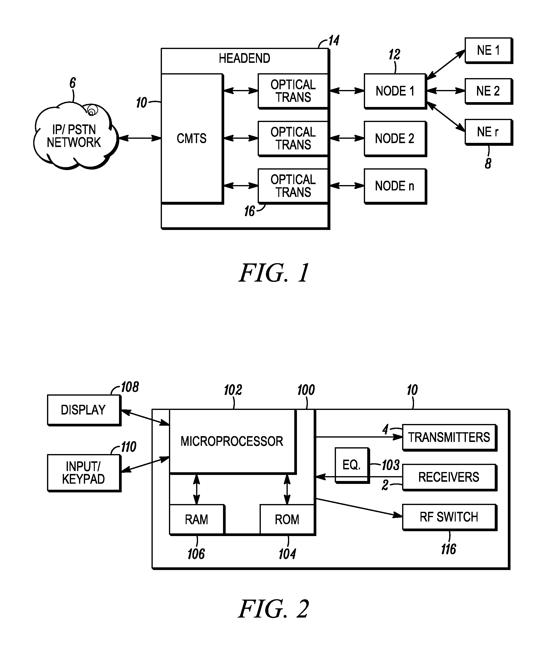
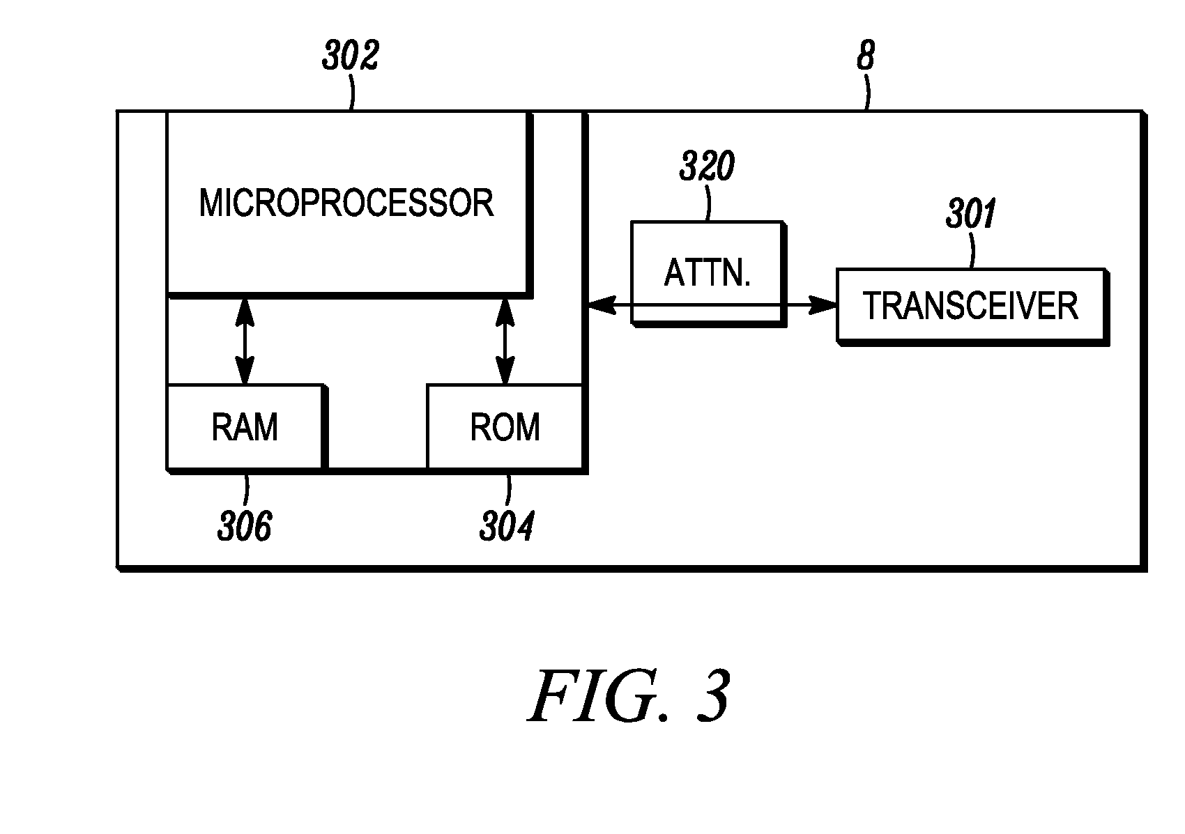
[0023]The invention provides an effective ability to maximize the data throughput of each network element subscriber (and the CMTS total throughput) at the time each network element registers with the CMTS. The CMTS uses logical channels to help perform this task. Network elements are assigned (re-registered), using instructions from the CMTS, such as the upstream channel override protocol, to the logical channel that supports the modulation error ratio (MER) or signal to noise ratio (SNR) threshold that each network element meets or exceeds when it registers. If the network element is already on the correct channel it will remain there. This way the network element is transmitting at its best modulation mode and therefore can maximize its data passing. This algorithm can be performed on any CMTS product used for high speed internet access.

[0024]The network can differentiate cable modems by Modulation Error Ratio (MER) which is a primary determinant in the modulation rate (QPSK, 16Q...


PUM


Abstract

A network element is registered on a physical channel and a first logical channel. The network controller receives ranging messages from which network element parameters associated with the network element are determined, and the network determines if the network element is better suited for a different logical channel on the network. The network controller provides an upstream channel change override signal to the network element, instructing the network element to re-register to another logical channel.

Description

FIELD OF THE INVENTION[0001]This disclosure is directed toward improving throughput for a network element in a network.BACKGROUND OF THE INVENTION[0002]Cable television systems have been in widespread use for many years and extensive networks have been developed. The extensive and complex networks are often difficult for a cable operator to manage and monitor. A typical cable network generally contains a headend which is usually connected to several nodes which provide content to a cable modem termination system (CMTS) containing several receivers, each receiver connects to several modems of many subscribers, e.g., a single receiver may be connected to hundreds of modems which vary widely in communication characteristics. In many instances several nodes may serve a particular area of a town or city. The modems communicate to the CMTS via upstream communications on a dedicated band of frequency.[0003]Cable networks are also increasingly carrying signals which require a high quality a...

Claims


Application Information

Patent Timeline
Patent Type & Authority Applications(United States)
IPC IPC(8): G06F15/173
CPCH04L27/34H04L41/0816H04L12/2872H04L12/2898H04L12/2801H04L41/5025
Inventor THIBEAULT, BRIAN K.COOPER, MICHAEL J.MORAN, JOHN L.NIKOLA, STEVE F.
Owner GENERAL INSTR CORP
Why Eureka
Try Eureka