Real-Time Solar Observations

a solar and real-time technology, applied in the field of real-time solar observations, can solve problems such as noticeable errors in prediction

Inactive Publication Date: 2013-02-21
QATAR FOUND
View PDF1 Cites 9 Cited by
  • Summary
  • Abstract
  • Description
  • Claims
  • Application Information

AI Technical Summary

Problems solved by technology

However, since these times are based on prediction, such predictions can have noticeable errors, for example up to thirty minutes of error.

Method used


Image

  • Real-Time Solar Observations
  • Real-Time Solar Observations
  • Real-Time Solar Observations

Examples


Embodiment Construction

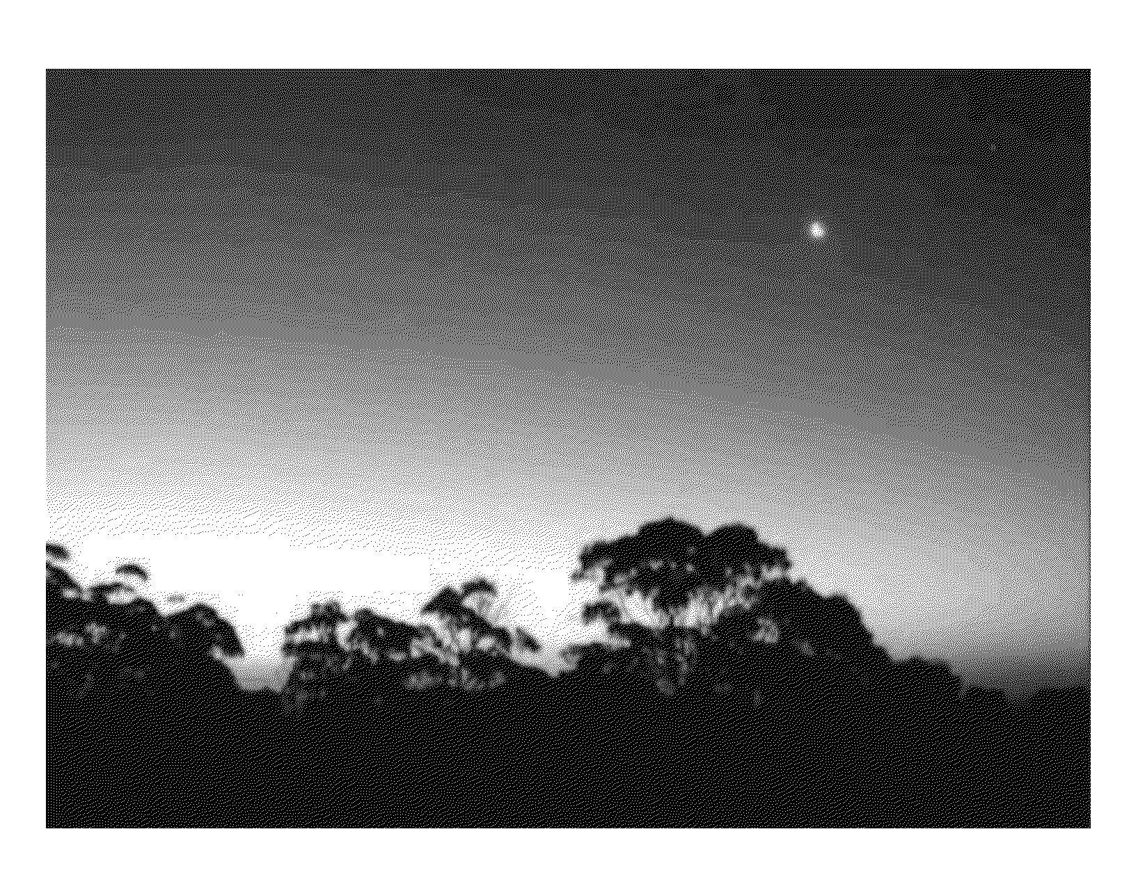
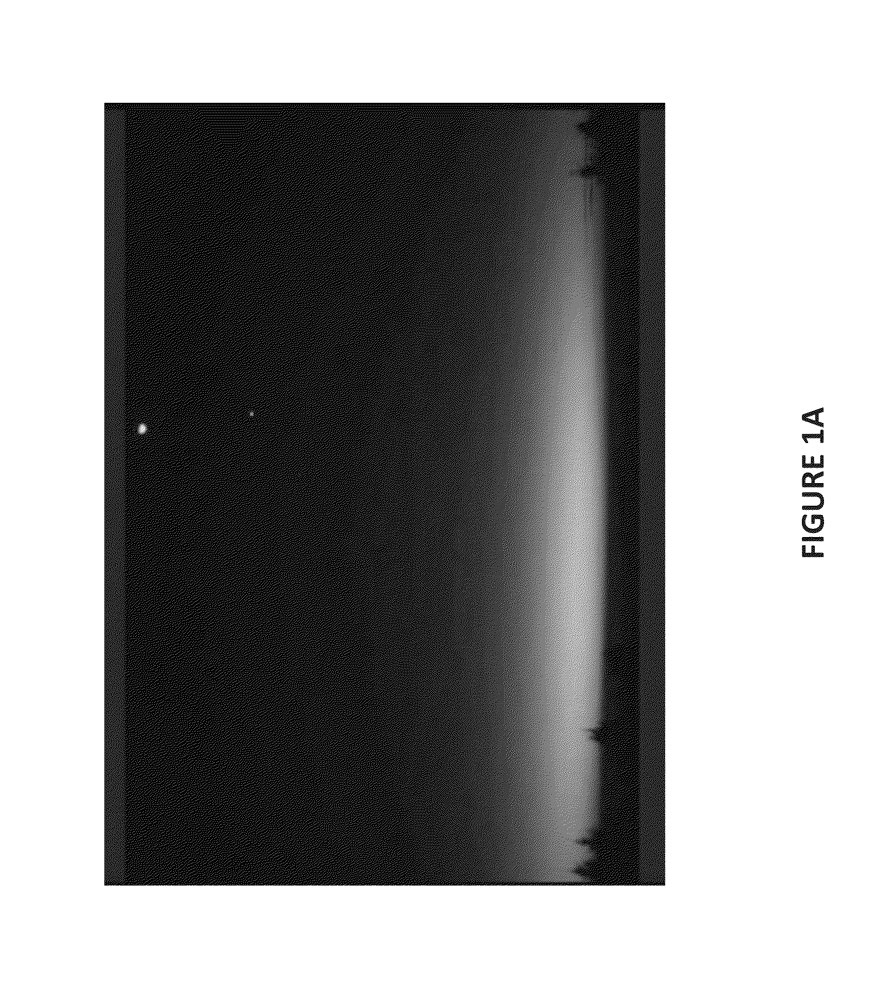
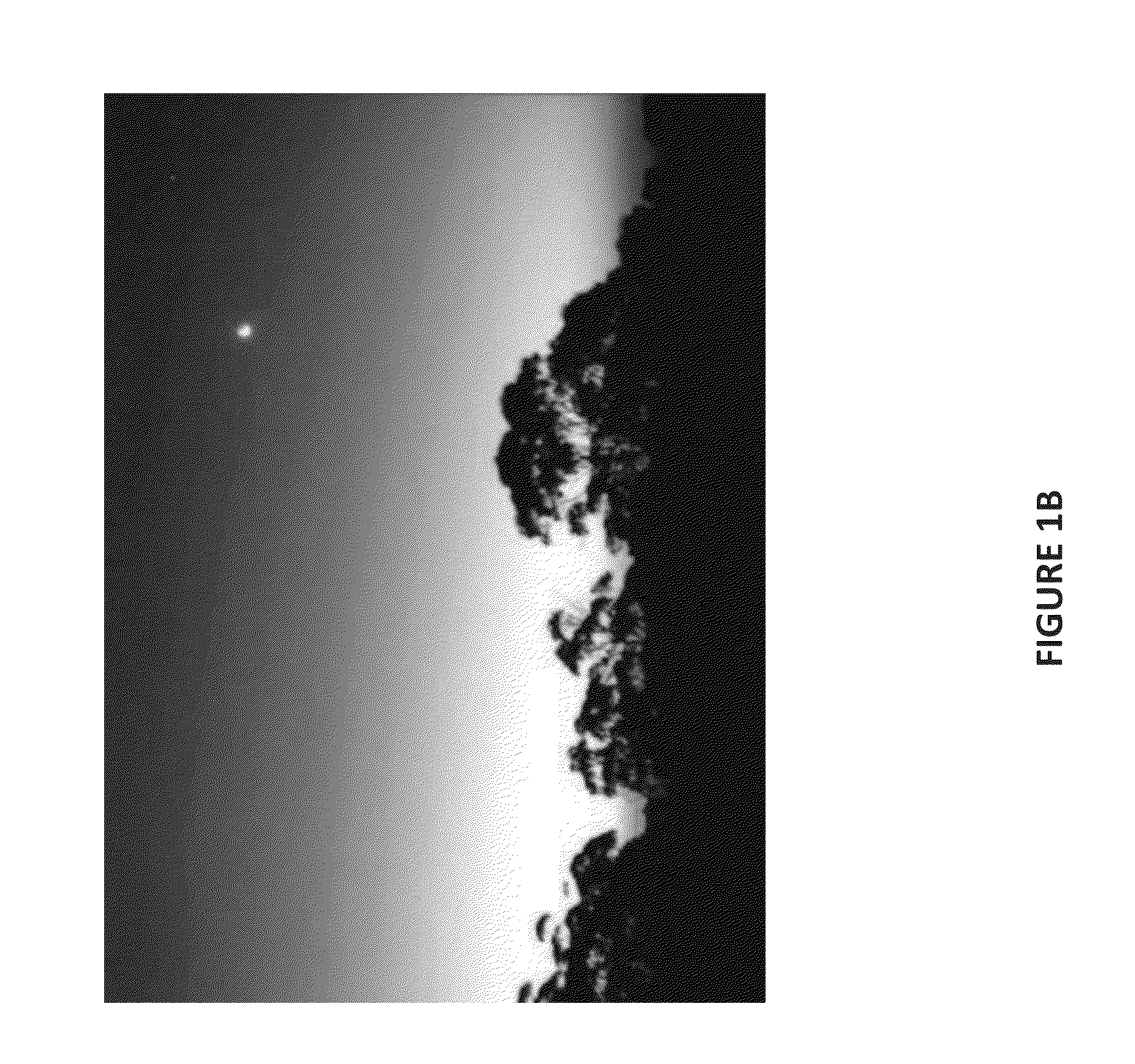
[0024]FIGS. 1A, 1B and 1C illustrate the start of the sunrise period; FIGS. 1A and 1B are photographs of the sun rising above the eastern horizon, and FIG. 1C is a schematic version thereof. The start of the sunrise period is defined by the time when a band of white light is visible above the eastern horizon. As will be seen in FIG. 1C, horizon 2 is illustrated, with a band of white light 4 appearing in the sky 6 just above the horizon 2.

[0025]FIG. 1D illustrates an image of a possible false sunrise, in which dust particles in the atmosphere reflect light from a pre-sunrise sun into the field of view of the observer

[0026]In FIGS. 2A and 2B, the end of the sunrise period is shown. As in FIG. 1A, FIG. 2A shows a photograph and FIG. 2B is a schematic illustration. The end of the sunrise period is defined as the point at which the solar disc 8 is completely visible above the eastern horizon 2 in the sky 6. The extent of the solar disc 8 does not extend below the eastern horizon; the sol...


PUM


Abstract

A system for real-time solar observation comprises an optical detector operable to detect sunlight and to produce image data from detected sunlight, a shadow detector operable to produce image data relating to a shadow cast by a reference object, and a controller operable to receive image data from the optical detector and from the shadow detector. The controller is operable to determine at least one of a sunrise period, a midday period and a sunset period in dependence upon received image data.

Description

[0001]The present invention relates to real-time solar observation, and, in particular, to systems and methods for detecting sun position in real time.BACKGROUND[0002]It is often desirable to know the exact position of the sun in the sky. For example, followers of the Islamic religion, and of other religions, have prayer times and fasting times dependent on the position of the sun. It is, therefore, desirable to be able to know the exact timing of particular solar positions. For example, the beginning and ending of sunrise, the beginning and ending of the midday sun, and the beginning and ending of sunset are all important points in the Islamic prayer and fasting day.[0003]Currently, there are many methods, charts and devices available to a user for predicting the timing of the sun's position. For example, using knowledge of the rotation of the earth about its own axis, and its rotation about the sun, it is possible to predict the timing of the important times of the solar day and p...

Claims


Application Information

Patent Timeline
Patent Type & Authority Applications(United States)
IPC IPC(8): H04N7/18G06K9/62
CPCG06K9/00697G06V20/38
Inventor AL-MAADID, LOLWA ALI SULTAN
Owner QATAR FOUND
Why Eureka
Try Eureka