Hysteroscopes with curved tips

a hysteroscope and tip technology, applied in the field of hysteroscopes, can solve problems such as unsatisfactory operation configuration

Active Publication Date: 2013-02-21
HD MEDICAL ELECTRONIC PROD INC
View PDF46 Cites 10 Cited by
  • Summary
  • Abstract
  • Description
  • Claims
  • Application Information

AI Technical Summary

Problems solved by technology

While a straight shaft 19 serves these purposes, this configuration is not ideal for operations...

Method used


Image

  • Hysteroscopes with curved tips
  • Hysteroscopes with curved tips
  • Hysteroscopes with curved tips

Examples


Embodiment Construction

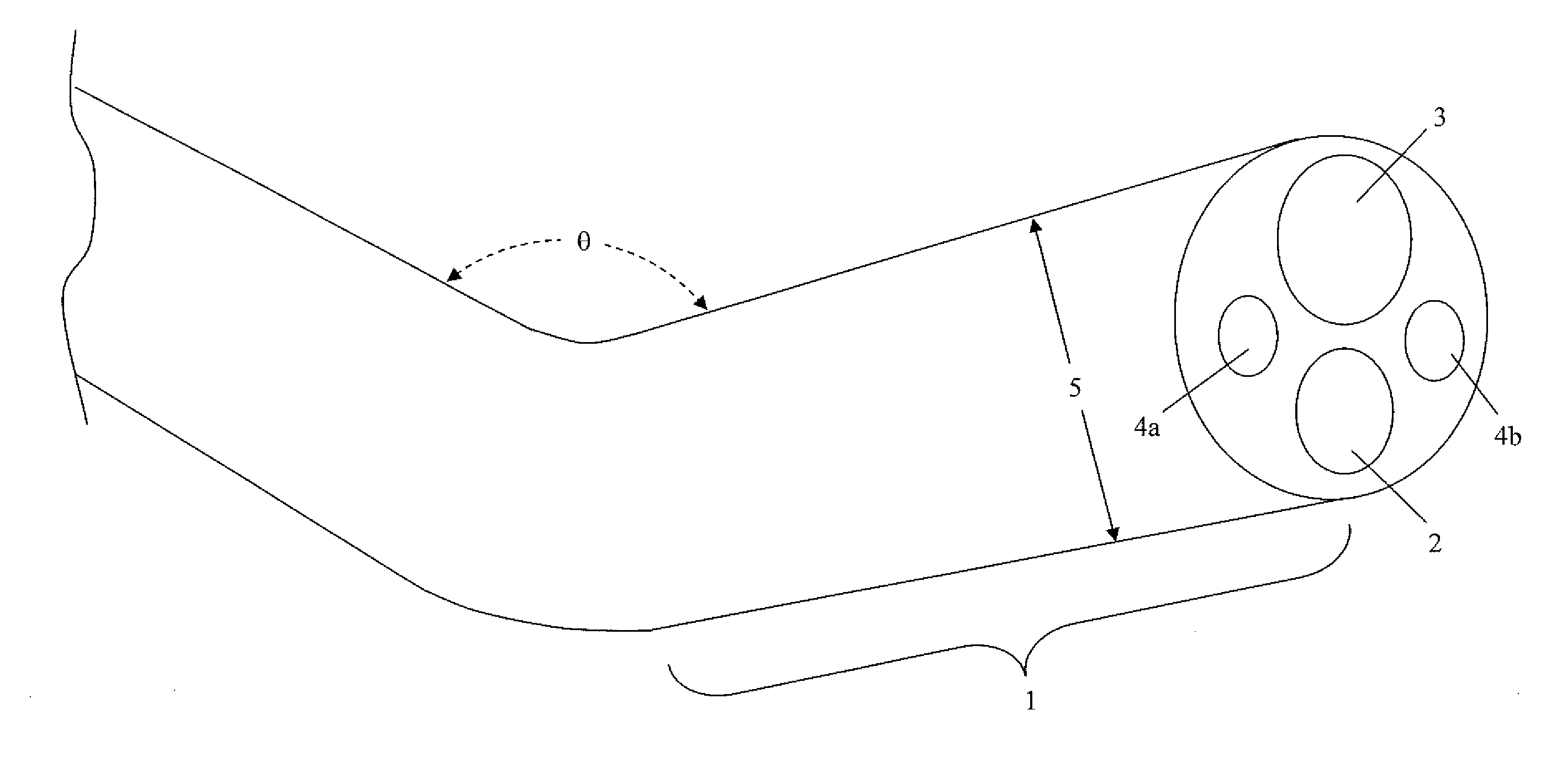
[0015]Embodiments of the invention relate to hysteroscopes designed and constructed so that a physician can use these instruments safely and with minimal discomfort to the female patient, and be able to insert the scope through the vagina and cervix into the uterine cavity for therapeutic or diagnostic medical purposes with relative ease. Specifically, hysteroscopes in accordance with embodiments of the invention relate to a bent tip at the distal end to facilitate viewing and access side walls or conual areas of a uterus.

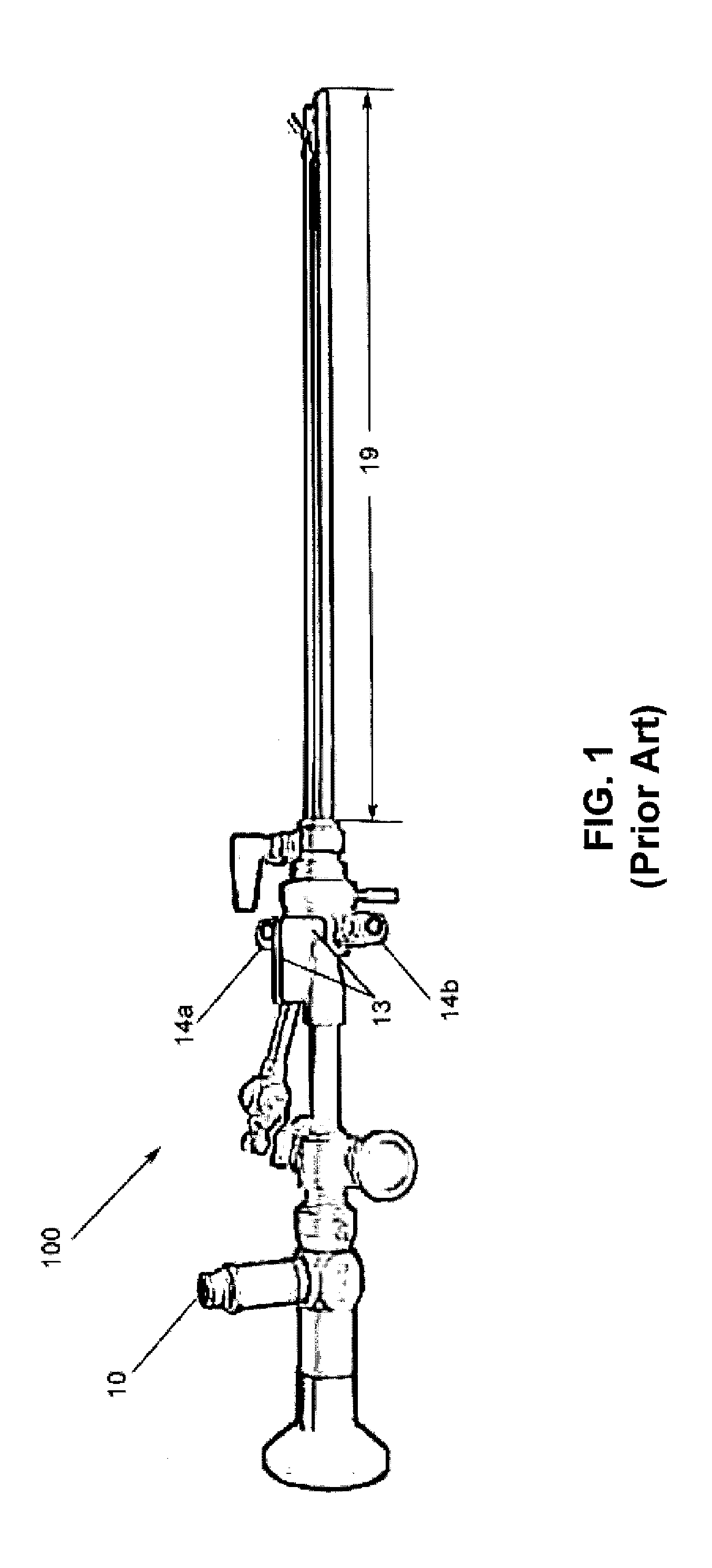
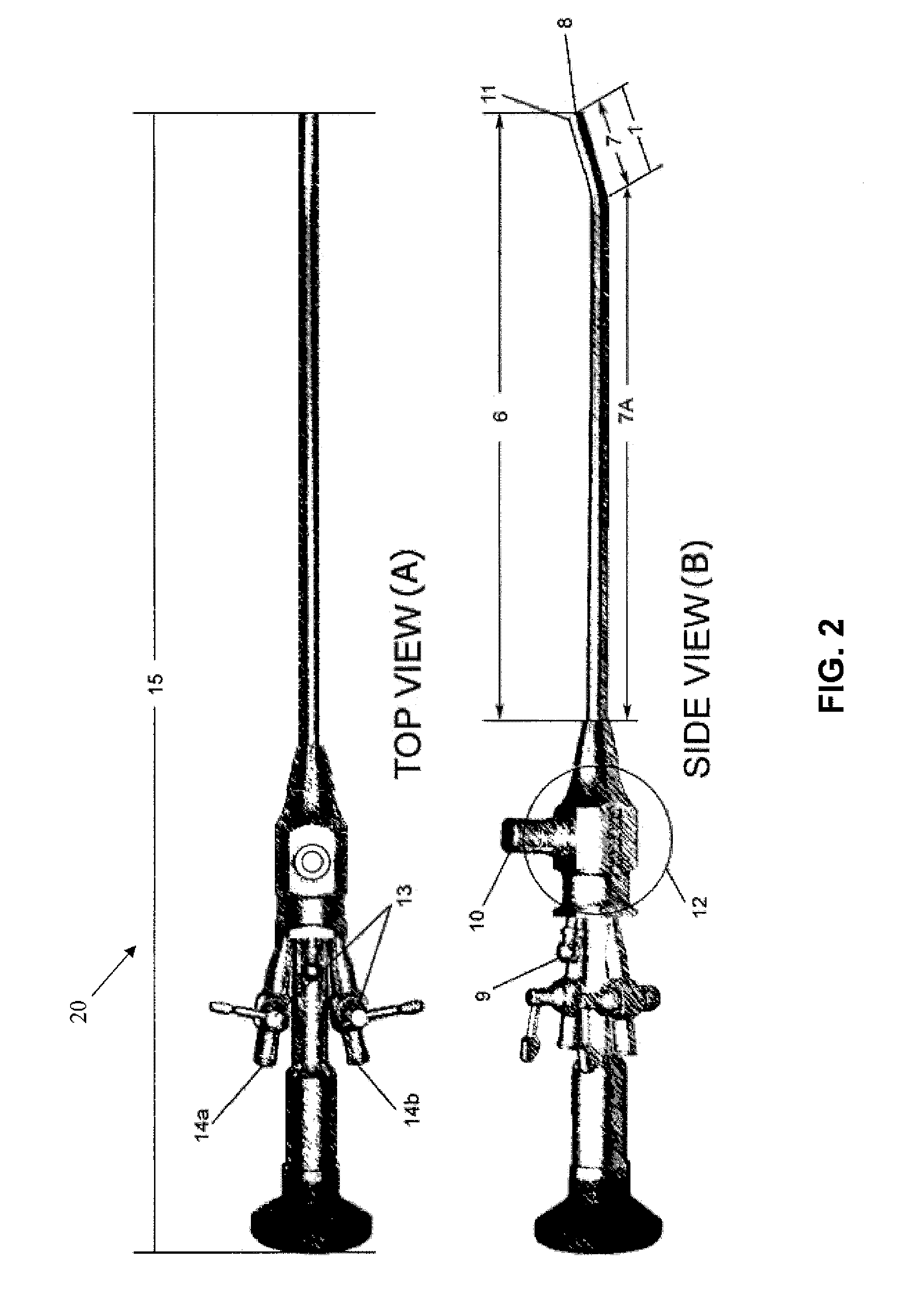
[0016]FIGS. 2A and 2B show one example of a hysteroscope in accordance with one embodiment of the invention. FIG. 2A shows a top view of a hysteroscope 20, while FIG. 2B shows its side view. As shown in FIG. 2B, the hysteroscope 20 may include conventional parts, such as fluid inlet and outlet 14a and 14b, bilateral (off and on) valves 13, a light source connector 10, an operating channel 9, and a shaft 11. The fluid inlet and outlet 14a and 14b are for fluid circu...


PUM


Abstract

A hysteroscope includes a shaft comprising a fiber optic light channel, an operating channel, and two fluid circulating channels; and a zero-angle lens disposed at an distal end of the fiber optic light channel, wherein a distal section of the shaft has a bent section, and wherein the bent section has a deflection angle of about 5-40 degrees relative to a longitudinal axis of the remaining section of the shaft.

Description

CROSS REFERENCE TO RELATED APPLICATIONS[0001]This claims the benefits of U.S. Provisional Patent Application No. 61 / 525,414, filed on Aug. 19, 2011, the disclosure of which is incorporated by reference in its entirety.BACKGROUND OF INVENTION[0002]1. Field of the Invention[0003]This invention relates to medical devices, particularly hysteroscopes.[0004]2. Background Art[0005]Hysteroscopy is a procedure to inspect the uterine cavity for the diagnosis of intrauterine pathology. The procedures may include surgical intervention (operative hysteroscopy). In performing hysteroscopy, an endoscope (a hysteroscope) is inserted through the cervix into the uterus. A hysteroscope carries optical fibers or light channels and inflow and outflow channels for insufflation of the uterine cavity. In addition, an operating channel may be included to allow scissors, graspers or biopsy instruments to be used to perform operations.[0006]FIG. 1 shows an example of a conventional hysteroscope. As shown, a h...

Claims


Application Information

Patent Timeline
IPC IPC(8): A61B1/303A61B1/12A61B1/07A61B1/018
CPCA61B1/00179A61B1/012A61B1/00071A61B1/303A61B1/00195A61B1/015A61B1/07
Inventor DAILY, HAROLD I.YIM, ANDY C.
Owner HD MEDICAL ELECTRONIC PROD INC
Why Eureka
Try Eureka