
Locking Pin with Spring Retention Mechanism

a technology of locking pin and spring retention mechanism, which is applied in the field of rigging, can solve the problems of cumbersome prior art approach to securing the load pin and time-consuming prior art approach

Active Publication Date: 2013-02-28
BRIGHT TECH CO LTD
View PDF9 Cites 10 Cited by
  • Summary
  • Abstract
  • Description
  • Claims
  • Application Information

AI Technical Summary

Benefits of technology

The patent provides a new way to keep a load pin secure and easily removable, which allows for faster and easier use compared to previous methods. Additionally, the load pin can be cycled through a high number of locking and unlocking cycles without needing to replace any hardware.

Problems solved by technology

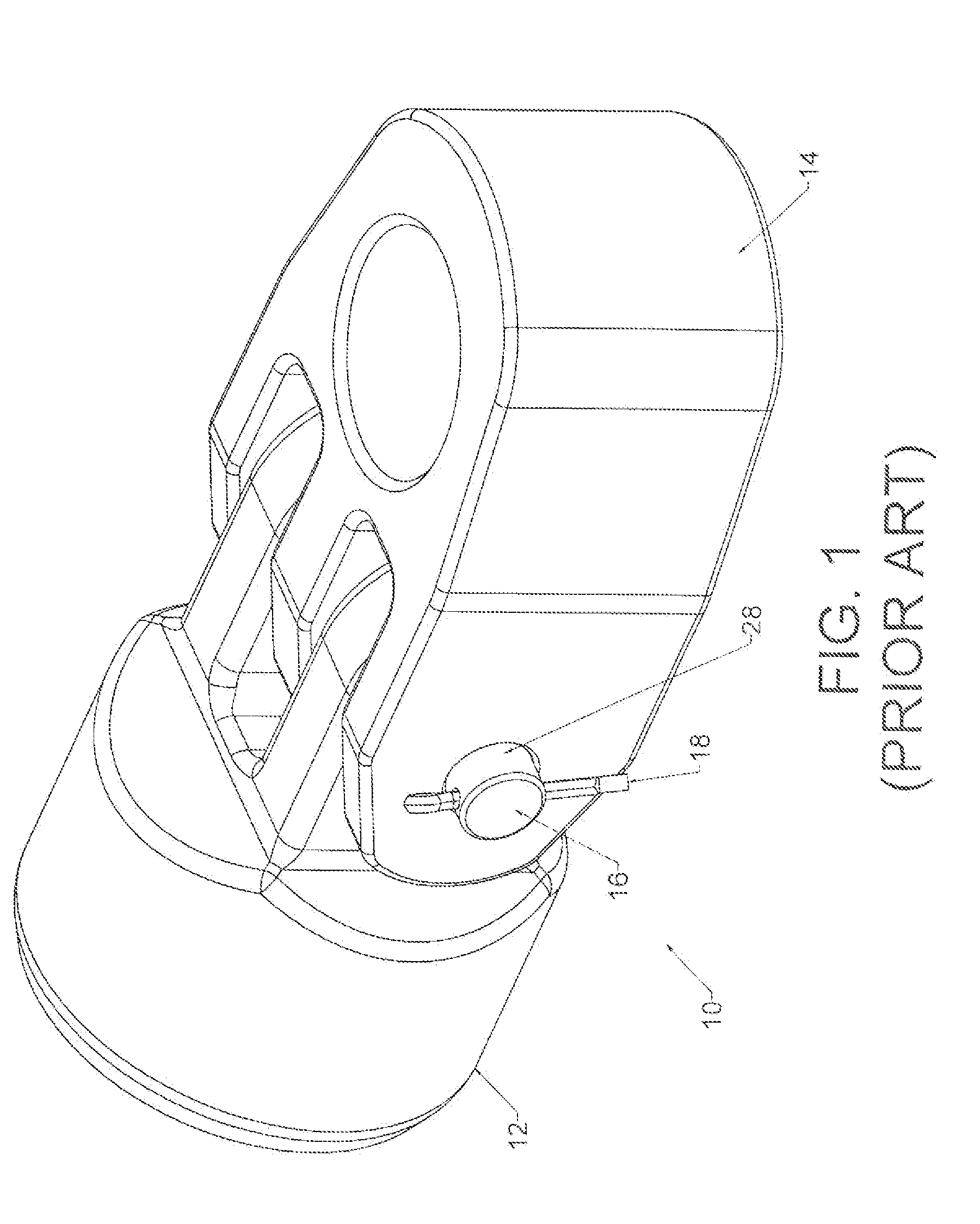
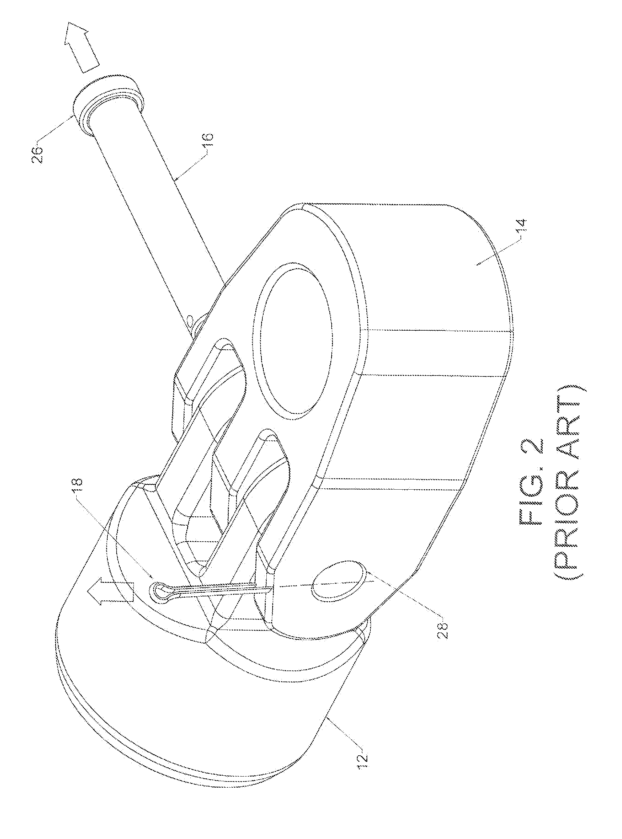
However, the prior art approach to securing the load pin is cumbersome in both the securing and the removing of the load pin.
In addition, the prior art approach includes numerous separate components that may easily be dropped or misplaced during the process.
Finally, the prior art approach is time consuming.

Method used


Image

  • Locking Pin with Spring Retention Mechanism
  • Locking Pin with Spring Retention Mechanism
  • Locking Pin with Spring Retention Mechanism

Examples


Embodiment Construction

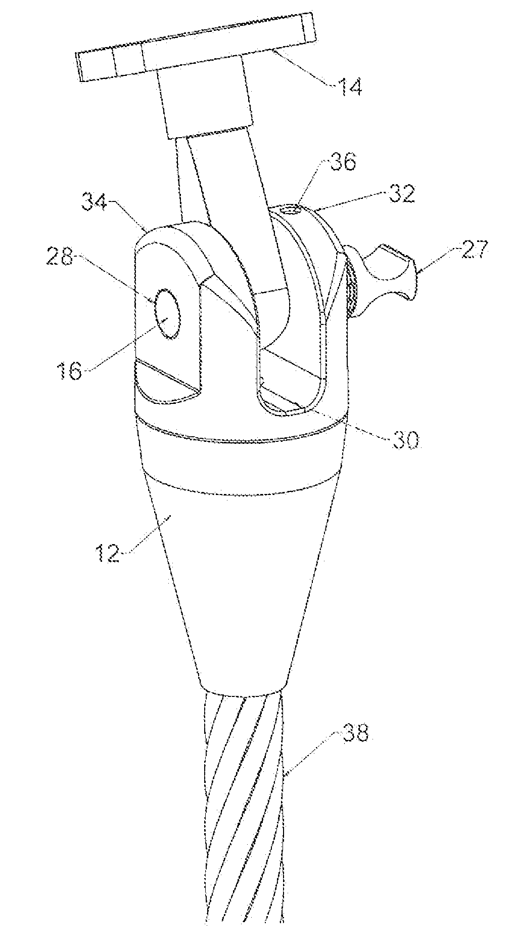
[0038]The present invention uses a load pin to selectively close an open span in a clevis joint. The invention includes a combination of retention features that secure the load pin in the closed position. Two or more separate motions are required to defeat the retention features, thereby eliminating the possibility of the pin being unlocked inadvertently.

[0039]The retention features use combinations of linear and rotary motion for the load pin. “Linear motion” is defined as pushing the load pin into or pulling the load pin out of the clevis joint. “Rotary motion” is defined as rotating the load pin about its central axis. Some constraints imposed by the retention features are purely linear, some arc purely rotational, and some are a combination of linear and rotational. When a constraint is stated as being a linear constraint, this should be understood to mean a predominately linear constraint. An example is a lug sliding in a keyway. This motion will be primarily linear. However, s...


PUM

PropertyMeasurementUnit
rotationaaaaaaaaaa
forceaaaaaaaaaa
timeaaaaaaaaaa

Abstract

A load pin and clevis joint for joining two or more mechanical components together. The load pin includes a retention feature that requires two separate motions to unlock the pin. In a locked state, the load pin is secured across both halves of a clevis joint so that it completely spans an open span between the two clevis halves. In the preferred embodiment, the two motions required to unlock the load pin are (1) moving the load pin linearly; and (2) rotating the load pin.

Description

CROSS-REFERENCES TO RELATED APPLICATIONS[0001]This is a non-provisional patent application that claims the benefit of an earlier-filed provisional patent application pursuant to the provisions of 37 C.F.R. §1.56(c). The earlier-filed application was assigned serial number 61 / 528,468. It was filed on Aug. 29, 2013 and listed the same inventor.STATEMENT REGARDING FEDERALLY SPONSORED RESEARCH OR DEVELOPMENT[0002]Not Applicable.MICROFICHE APPENDIX[0003]Not ApplicableBACKGROUND OF THE INVENTION[0004]1. Field of the Invention[0005]This invention relates to the field of rigging. More specifically, the invention comprises a load pin for joining two or more mechanical components together. The load pin includes multiple retention features that require two separate motions to unlock the pin.[0006]2.Description of the Related Art[0007]There are many different devices used for locking two or more separate components together. FIG. 1 shows one such device. Anchor 12 is to be joined to loading com...

Claims


Application Information

Patent Timeline
Patent Type & Authority Applications(United States)
IPC IPC(8): B23P11/00
CPCY10T29/49947F16G15/06
Inventor CAMPBELL, RICHARDHILBIG, DAVIDSEDILES, DAVIDWORTHAM, KRISTOPHER
Owner BRIGHT TECH CO LTD
Learn More