Electric linear motion actuator and electric brake system

a technology of linear motion and actuator, which is applied in the direction of brake types, mechanical equipment, brakes, etc., can solve the problems of difficult to accurately linearly move the output member to the required position, and difficult to so as to accurately generate produce the required braking force

Active Publication Date: 2013-02-28
NTN CORP
View PDF9 Cites 36 Cited by
  • Summary
  • Abstract
  • Description
  • Claims
  • Application Information

AI Technical Summary

Benefits of technology

[0023]Since the electric linear motion actuator according to the present invention includes a load sensor mounted in the motion converter mechanism to detect the pushing force with which the output member linearly drives the driven member, it is possible to directly detect the braking force applied by the driven m...

Problems solved by technology

With the arrangements in which the required braking force is produced by applying the predetermined current to the motor or rotating the motor to the predetermined angular position, it is difficult to accurately linearly move the output...

Method used


Image

  • Electric linear motion actuator and electric brake system
  • Electric linear motion actuator and electric brake system
  • Electric linear motion actuator and electric brake system

Examples


Embodiment Construction

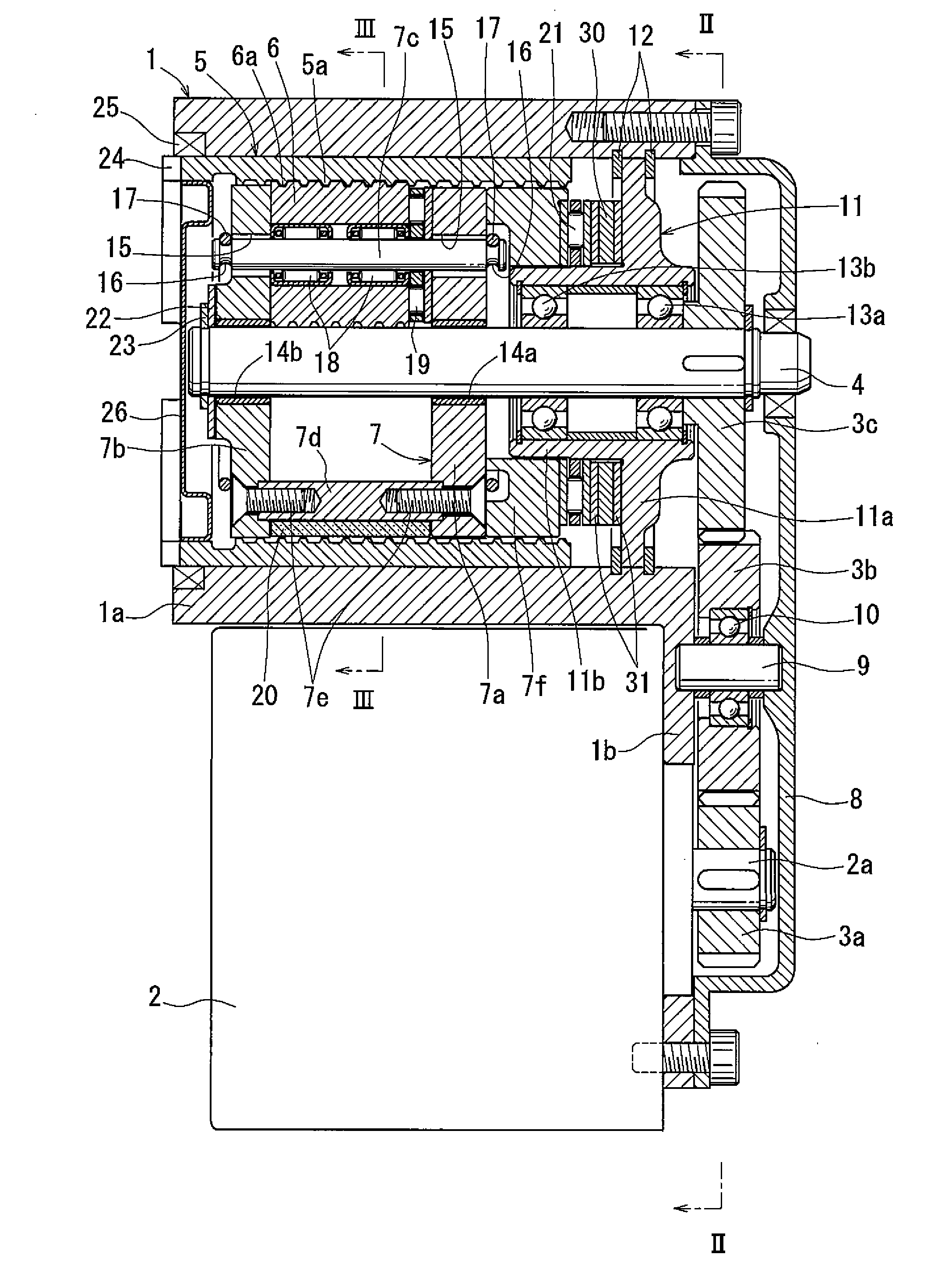
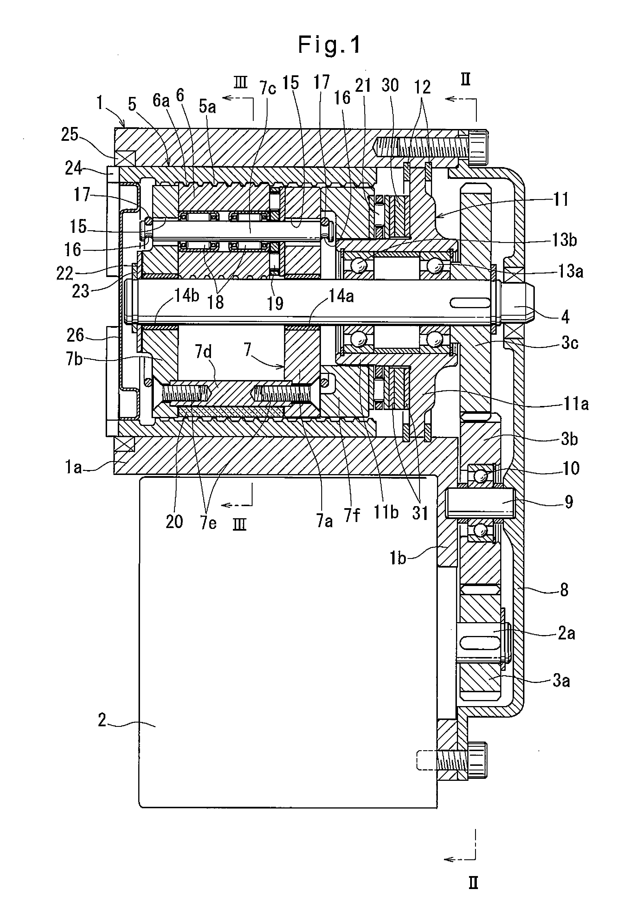
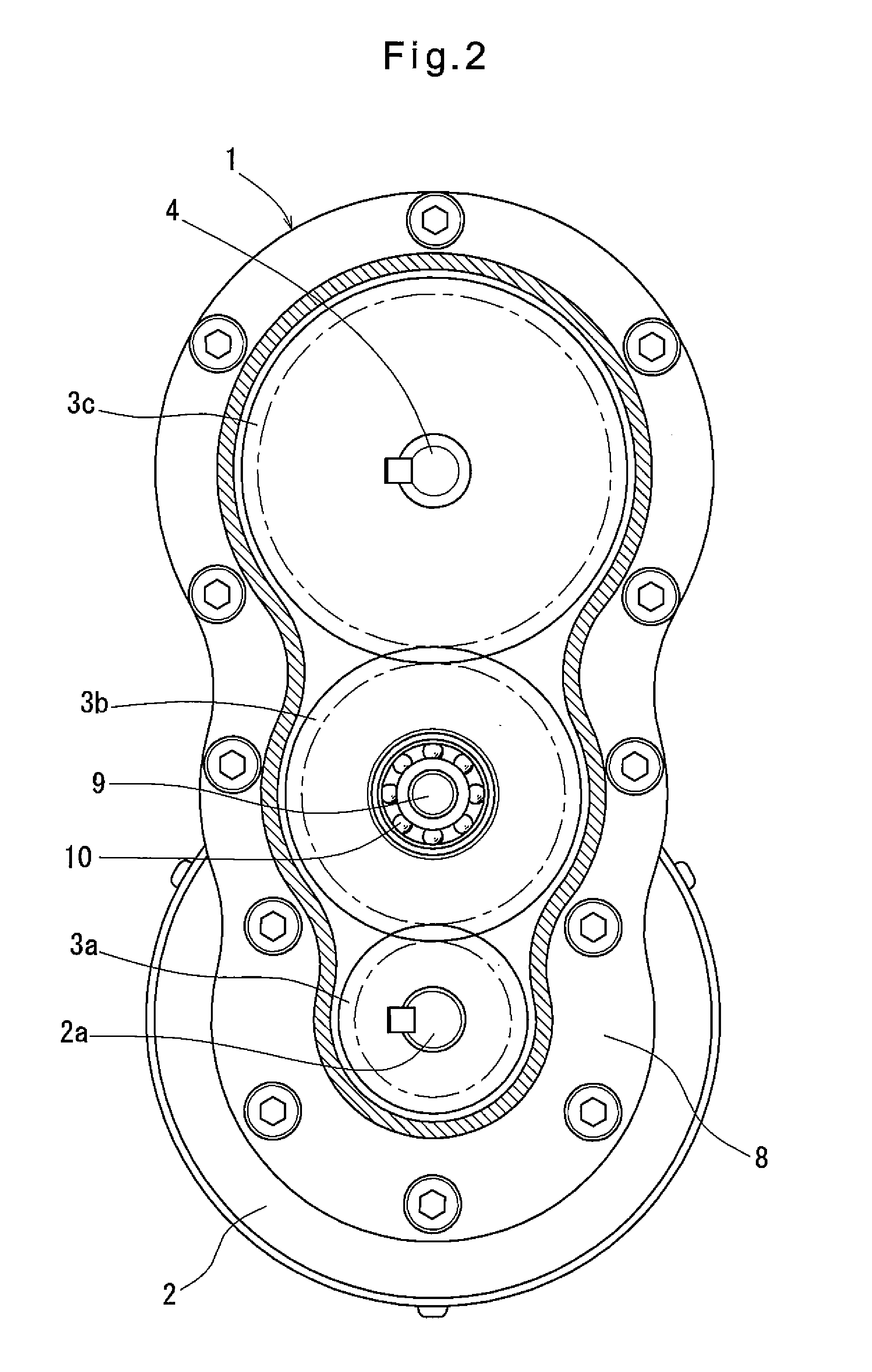
[0033]The electric linear motion actuator embodying the present invention is now described with referenced to the drawings. As shown in FIGS. 1 to 3, the actuator includes a housing 1 having a cylindrical portion 1a formed with a flange 1b at one end thereof to extend to one side. The flange 1b carries an electric motor 2 so as to extend parallel to the cylindrical portion 1a. The electric motor 2 has a rotor shaft 2a whose rotation is transmitted to a rotary shaft 4 extending along a center axis of the cylindrical portion through gears 3a, 3b and 3c. The actuator further includes an outer ring member 5 fitted in the radially inner surface of the cylindrical portion 1a, four planetary rollers 6 disposed between the outer ring member 5 and the rotary shaft 4 and rotatably supported by a carrier 7. When the rotary shaft 4 rotates, the planetary rollers 6 revolve around the rotary shaft while rotating about their respective center axes. The actuator further includes a motion converter ...


PUM


Abstract

An electric brake system is proposed which includes an electric linear motion actuator and can generate the required braking force with high accuracy. A load sensor (30) is provided in a motion converting mechanism of the actuator which converts the rotary motion of a rotary shaft (4) to which the rotation of an electric motor (2) is transmitted to linear motion of an outer ring member (5) as an output member. The load sensor (30) detects the pushing force with which the outer ring member (5) linearly drives a driven member. With this arrangement, if the driven member is a braking member of an electric brake system, it is possible to directly detect the braking force applied by the driven member and thus to accurately generate the required braking force.

Description

TECHNICAL FIELD[0001]The present invention relates to an electric linear motion actuator for converting the rotary motion of an electric motor to linear motion, thereby linearly driving a driven member, and an electric brake system wherein a braking is pressed against a braked member by means of the electric linear motion actuator.BACKGROUND ART[0002]A known electric linear motion actuator for converting the rotary motion of an electric motor to linear motion, thereby linearly driving a driven member, includes a motion converter mechanism such as a slide screw mechanism, a ball-screw mechanism or a ball-ramp mechanism for converting the rotary motion of the rotor shaft of an electric motor or of a rotary member to which the rotation of the rotor shaft is transmitted to the linear motion of an output member for linearly driving the driven member. Many of this type of electric linear motion actuators include a gear type speed reducer such as a planetary gear type speed reducer so that...

Claims


Application Information

Patent Timeline
IPC IPC(8): F16H25/22F16D55/00F16D65/18F16D65/14F16D121/24F16D125/40F16H19/02F16H25/20
CPCF16D65/18F16D2121/24F16D2125/40F16D2125/48Y10T74/18568F16D2129/08F16H25/2252F16H25/2021Y10T74/18576F16D2127/06
Inventor MURAMATSU, MAKOTOYAMASAKI, TATSUYAEGUCHI, MASAAKIGOTO, TOMOMI
Owner NTN CORP
Why Eureka
Try Eureka