Edge accuracy in a capacitive sense array

a capacitive sense array and accuracy technology, applied in capacitance measurement, resistance/reactance/impedence, instruments, etc., can solve the problems of systematic centroid offset along the edges of the panel, the accuracy variation between a center area and an edge area, and the conventional design of considerable position tracking error near the edges of the touch screen

Active Publication Date: 2013-02-28
PARADE TECH
View PDF7 Cites 71 Cited by
  • Summary
  • Abstract
  • Description
  • Claims
  • Application Information

AI Technical Summary

Problems solved by technology

However, conventional designs exhibit considerable position tracking error near the edges of the touch screen.
One problem with this conventional design is that accuracy variation between a center area and an edge area.
So, without a

Method used


Image

  • Edge accuracy in a capacitive sense array
  • Edge accuracy in a capacitive sense array
  • Edge accuracy in a capacitive sense array

Examples


Embodiment Construction

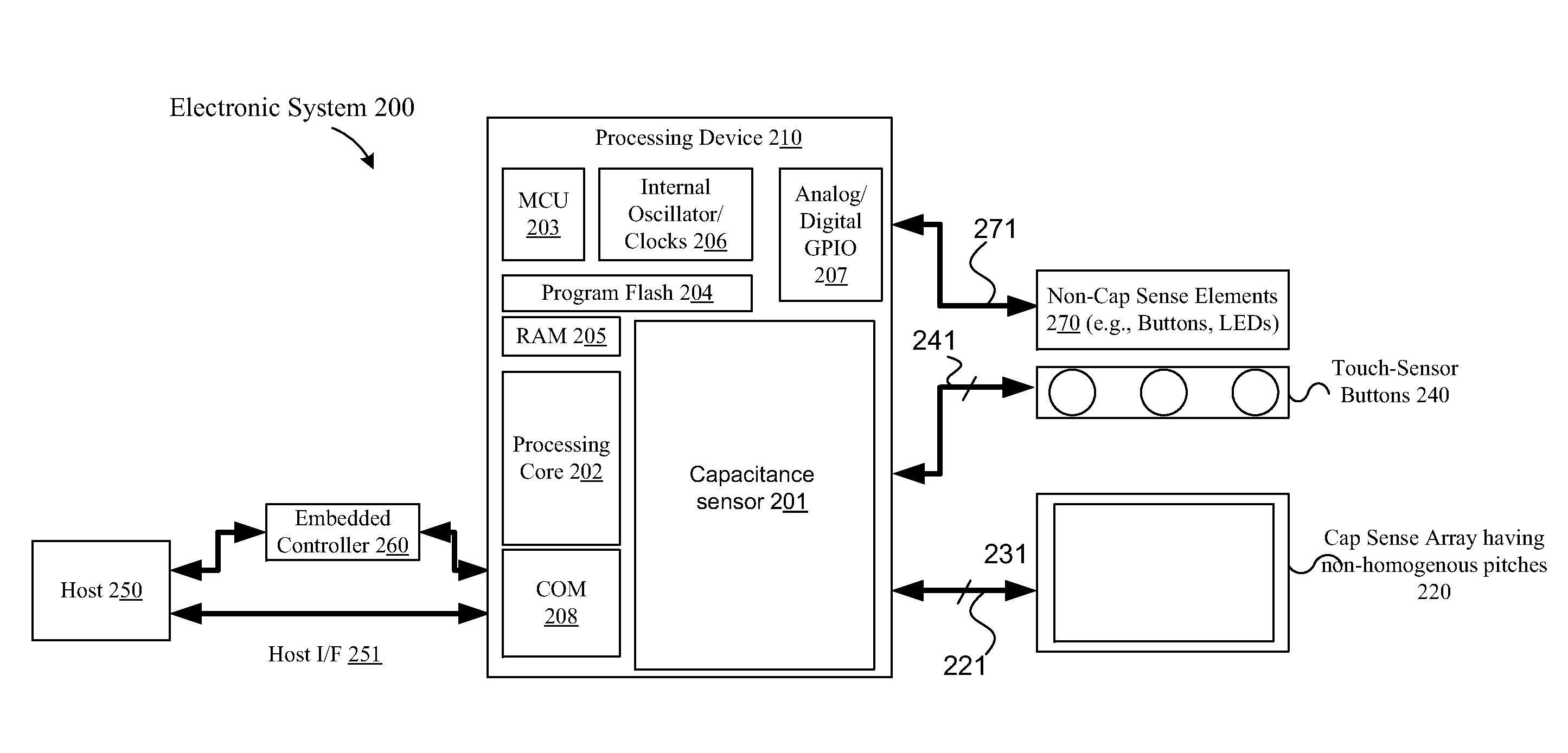
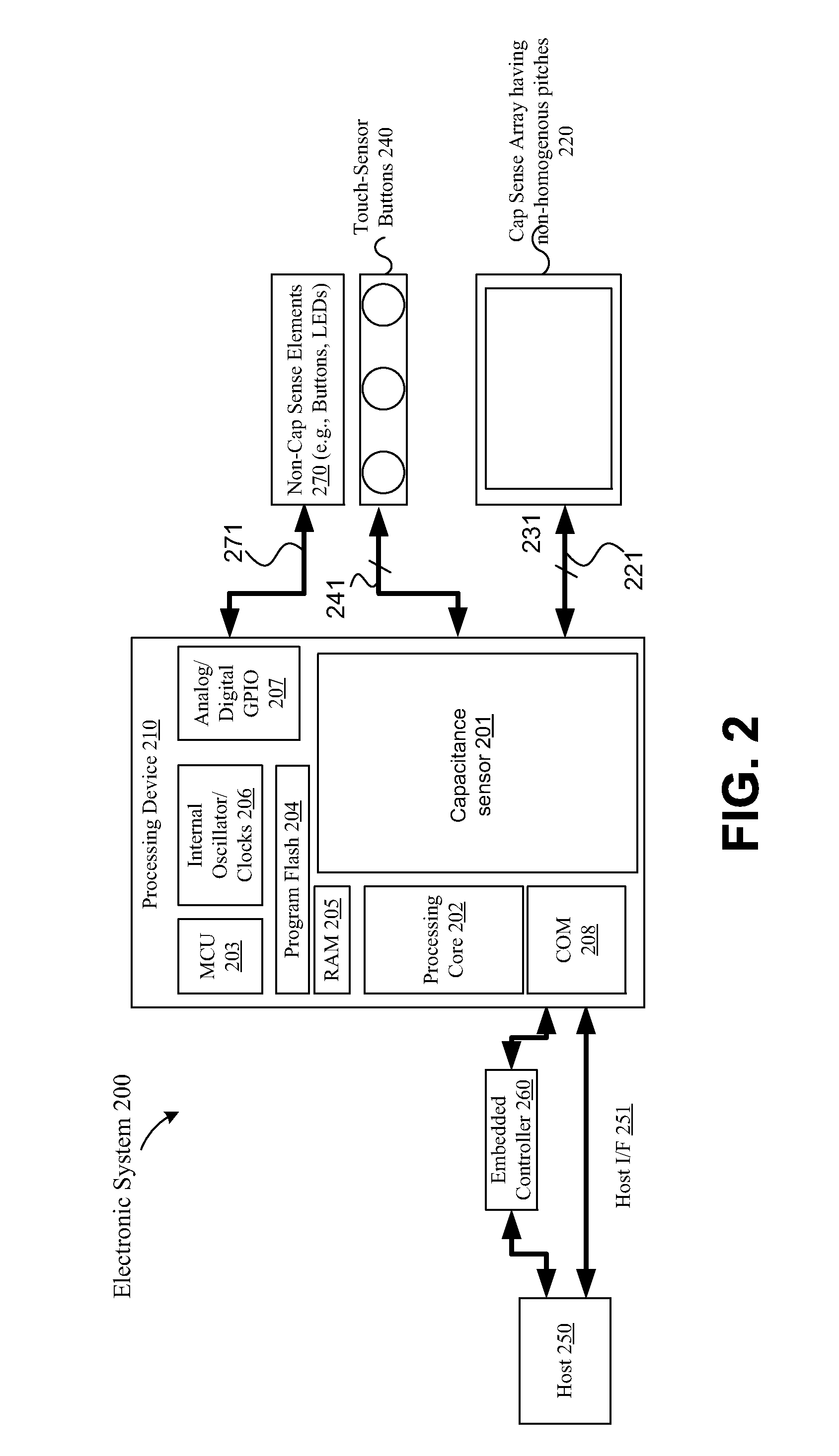
[0021]A capacitive sense array configured to improve edge accuracy in detecting a presence of a conductive object is described. In one embodiment, a capacitive sense array includes at least a first set of sense elements having non-homogenous pitches disposed in a first longitudinal axis of the capacitive sense array. The pitch as defined in the present invention includes width of the sense elements and spacing between the sense elements.

[0022]The embodiments described herein are configured to improve edge accuracy of the capacitive sense array.

[0023]As described above, in touch panel applications, accuracy is defined as error between the location of a conductive object on or in proximity to the touch panel and the location sensed by the touch panel. The sensed, or calculated location is based on the overall signal magnitude and profile of the presence of the conductive object detected by the capacitive sense circuitry. For example, a single finger touch generates signals across a ne...


PUM


Abstract

A capacitive sense array configured to improve edge accuracy in detecting a presence of a conductive object is described. In one embodiment, a capacitive sense array includes at least a first set of sense elements having non-homogenous pitches disposes in a first longitudinal axis of the capacitive sense array. The pitch includes width of the sense elements and spacing between the sense elements.

Description

RELATED APPLICATIONS[0001]This application claims the benefit of PCT / US11 / 48908, IP / US filed on 24 Aug. 2011.TECHNICAL FIELD[0002]This disclosure relates to the field of user interface devices and, in particular, to capacitive sense devices.BACKGROUND[0003]Capacitive sense arrays may be used to replace mechanical buttons, knobs and other similar mechanical user interface controls. The use of a capacitive sense element allows for the elimination of complicated mechanical switches and buttons, providing reliable operation under harsh conditions. In addition, capacitive sense elements are widely used in modern customer applications, providing new user interface options in existing products. Capacitive sense elements can be arranged in the form of a capacitive sense array for a touch-sensing surface. When a conductive object, such as a finger, comes in contact or close proximity with the touch-sensing surface, the capacitance of one or more capacitive touch sense elements changes. The c...

Claims


Application Information

Patent Timeline
IPC IPC(8): G01R27/26
CPCG06F3/0418G01R27/2605G06F3/044G06F3/0445
Inventor PENG, TAOCHAI, MIN CHIN
Owner PARADE TECH
Why Eureka
Try Eureka