Substrate for fingerprint contact

a fingerprint and substrate technology, applied in the field of substrates, can solve the problems of high assembly cost, difficult and complex assembly of the totally reflective optical fingerprint recognition system, and the likelihood of non-uniform reflected light, so as to improve the brightness of light, weaken unnecessary scattered light, and enhance the scattering

Active Publication Date: 2013-02-28
GINGY TECH
View PDF10 Cites 46 Cited by
  • Summary
  • Abstract
  • Description
  • Claims
  • Application Information

AI Technical Summary

Benefits of technology

[0014]In an embodiment of the disclosure, the above-mentioned film features hazed particles formed by the UV Coating or the mold discharging process, and the haze of the film approximately ranges from 85% to 95%. When light is emitted to the finger, the optical diffusing surface of the film helps to enhance the scattering of the light to make the light evenly emitted to the finger, thereby improving the brightness of the light. When the light contacts the finger, as a ridge of the finger contacts the optical diffusing surface, the light is reflected back directly, and the optical diffusing surface of the film is capable of weakening unnecessary scattered light to the optical imaging system when contacting the ridges of the finger. Meanwhile, in a chamber formed by a valley of the finger and the film, since the reflection and scattering of the light in the chamber may enhance the brightness, when the light is reflected and scattered back to the sensing element through the finger, a clear fingerprint pattern is transmitted to a sensing element of the optical imaging system, thereby enhancing the difference of the brightness and darkness of the fingerprint pattern.
[0015]For the substrate for fingerprint contact in an embodiment of the disclosure, a light incident angle and a light emergent angle of the substrate do not need to be adjusted accurately in the assembly, and only a focal length between the substrate and the optical imaging system is required to be determined

Problems solved by technology

Therefore, the assembly of the totally reflective optical fingerprint recognition system is difficult and complex, and the cost of the assembly is also high.
In addition, a light emitting element of the totally reflective optical fingerprint recognition system is a point light source, and if the light is not diffused through certain optical processing, the reflected light is likely to become non-uniform, resulting in an unclear image.
Therefore, when capturing a fing

Method used


Image

  • Substrate for fingerprint contact
  • Substrate for fingerprint contact
  • Substrate for fingerprint contact

Examples


Embodiment Construction

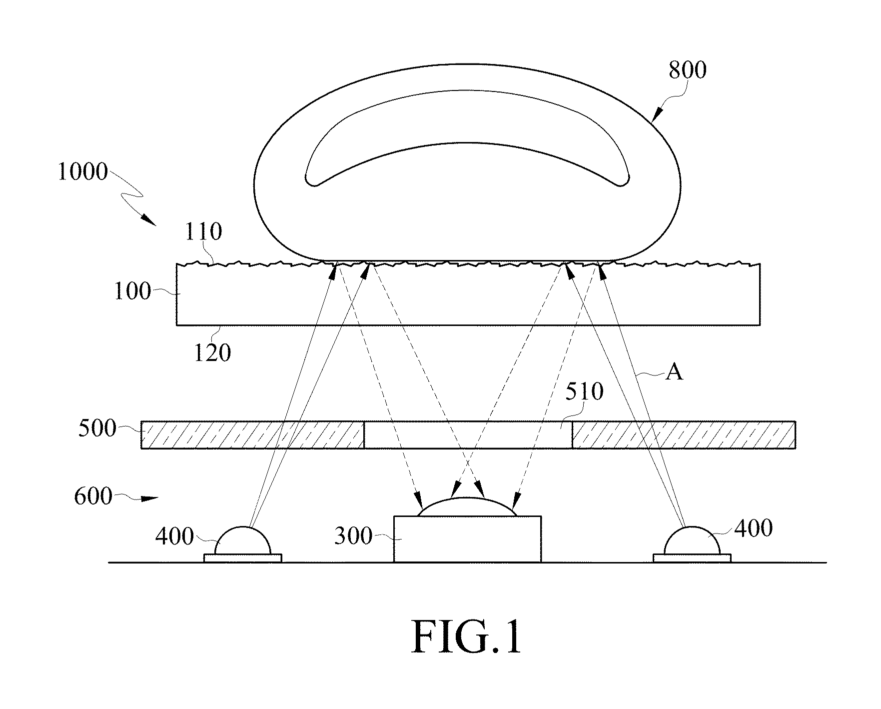
[0022]FIG. 1 is an overall structural view of a substrate for fingerprint contact according to an embodiment of the disclosure. In the embodiment shown in FIG. 1, a substrate 1000 includes a plate 100, and the plate 100 has a first surface 110 and a second surface 120. The first surface 110 is opposite to the second surface 120. The first surface 110 is an optical diffusing surface used for being contacted by a finger 800, and the second surface 120 faces an optical imaging system 600.

[0023]In this embodiment and parts of other embodiments, the optical diffusing surface of the first surface 110 and the plate 100 are integrally formed.

[0024]In an embodiment of the disclosure, the optical imaging system 600 includes two light emitting elements 400 and a sensing element 300. The light emitting elements 400 are used for emitting light to the plate 100, and the sensing element 300 faces the plate 100 and the sensing element 300 is used for capturing a fingerprint pattern of the finger 80...


PUM


Abstract

A substrate for fingerprint contact includes a plate, and the plate includes a first surface and a second surface. The first surface is an optical diffusing surface. The optical diffusing surface is used for being contacted by a finger, and features hazed particles. The second surface faces an optical imaging system. The optical diffusing surface of the plate helps to enhance light to be evenly emitted to the finger and weakens the unnecessary scattered light to the optical imaging system, so as to enhance the recognition rate of a fingerprint when the optical imaging system is used for intercept the light applied on a finger.

Description

CROSS-REFERENCE TO RELATED APPLICATIONS[0001]This non-provisional application claims priority under 35 U.S.C. §119(a) on Patent Application No(s). 100130376 filed in Taiwan, R.O.C. on Aug. 24, 2011, the entire contents of which are hereby incorporated by reference.BACKGROUND[0002]1. Technical Field[0003]The present disclosure relates to a substrate, and more particularly to a substrate for fingerprint contact.[0004]2. Related Art[0005]Identity recognition plays an important role as a goalkeeper in the state security, enterprise information management and home security. Biometrics identifies and confirms the identity of a person according to specific physiological characteristics. Generally, biometrics mainly consists of recognition through voice, face, iris, vein, and fingerprint at present. Fingerprints are made up of many rough and uneven ridges and valleys. The fingerprints of each person are unique, a faint possibility exists that different persons have identical fingerprints, a...

Claims


Application Information

Patent Timeline
IPC IPC(8): G06K9/00
CPCG06K9/00006G06K9/00046G06V40/1324G06V10/10
Inventor WU, CHIEN-HSINGCHOU, JUNG-TSUNG
Owner GINGY TECH
Why Eureka
Try Eureka