Enzymatic process and bioreactor using elongated structures for co2 capture treatment

a bioreactor and enzymatic process technology, applied in the field of co2containing gas treatment, can solve the problems of significant barrier to adoption of carbon capture technology on a large scale, such as cosub>2/sub>, and reduce the cost of capture, so as to improve the efficiency of co2 capture treatment.

Inactive Publication Date: 2013-02-28
CO2 SOLUTION
View PDF4 Cites 10 Cited by
  • Summary
  • Abstract
  • Description
  • Claims
  • Application Information

AI Technical Summary

Benefits of technology

[0008]The present invention responds to the above need by providing an enzymatic process and bioreactor using elongated structures to enhance CO2 capture treatments.

Problems solved by technology

Reduction of Green House Gases (GHG), such as CO2, is a challenging issue directly involving gas separation and capture processes.
A very significant barrier to adoption of carbon capture technology on a large scale is cost of capture.
This is an energy intensive process that involves heating the solvent to high temperature to strip the CO2 (and regenerate the solvent) for underground sequestration.
This large cost for the capture portion has, to present, made large scale CCS unviable; based on data from the IPCC, for instance, for a 700 megawatt (MW) pulverized coal power plant that produces 4 million metric tons of CO2 per year, the capital cost of conventional CO2 capture equipment on a retrofit basis would be nearly $800 million and the annual operating cost and plant energy penalty would be nearly $240 million.
A major limiting factor of gas separation is mass transfer, from the gas phase (effluent gas mixture) into the liquid phase (absorption solution) and vice-versa.
One challenge in the design and operation of enzymatic bioreactors is achieving efficient mass transfer and reaction rates while avoiding reduction of enzyme activity.
Enzyme activity can be hampered or even lost due to various factors such as temperature, pressures and destructive forces occurring inside a reactor.
It is a challenge to strike a balance between enzyme activity and favorable operating conditions for mass transfer and chemical reactions.

Method used


Image

  • Enzymatic process and bioreactor using elongated structures for co2 capture treatment
  • Enzymatic process and bioreactor using elongated structures for co2 capture treatment
  • Enzymatic process and bioreactor using elongated structures for co2 capture treatment

Examples


Embodiment Construction

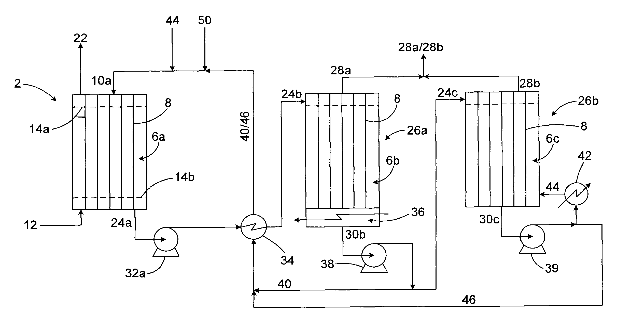
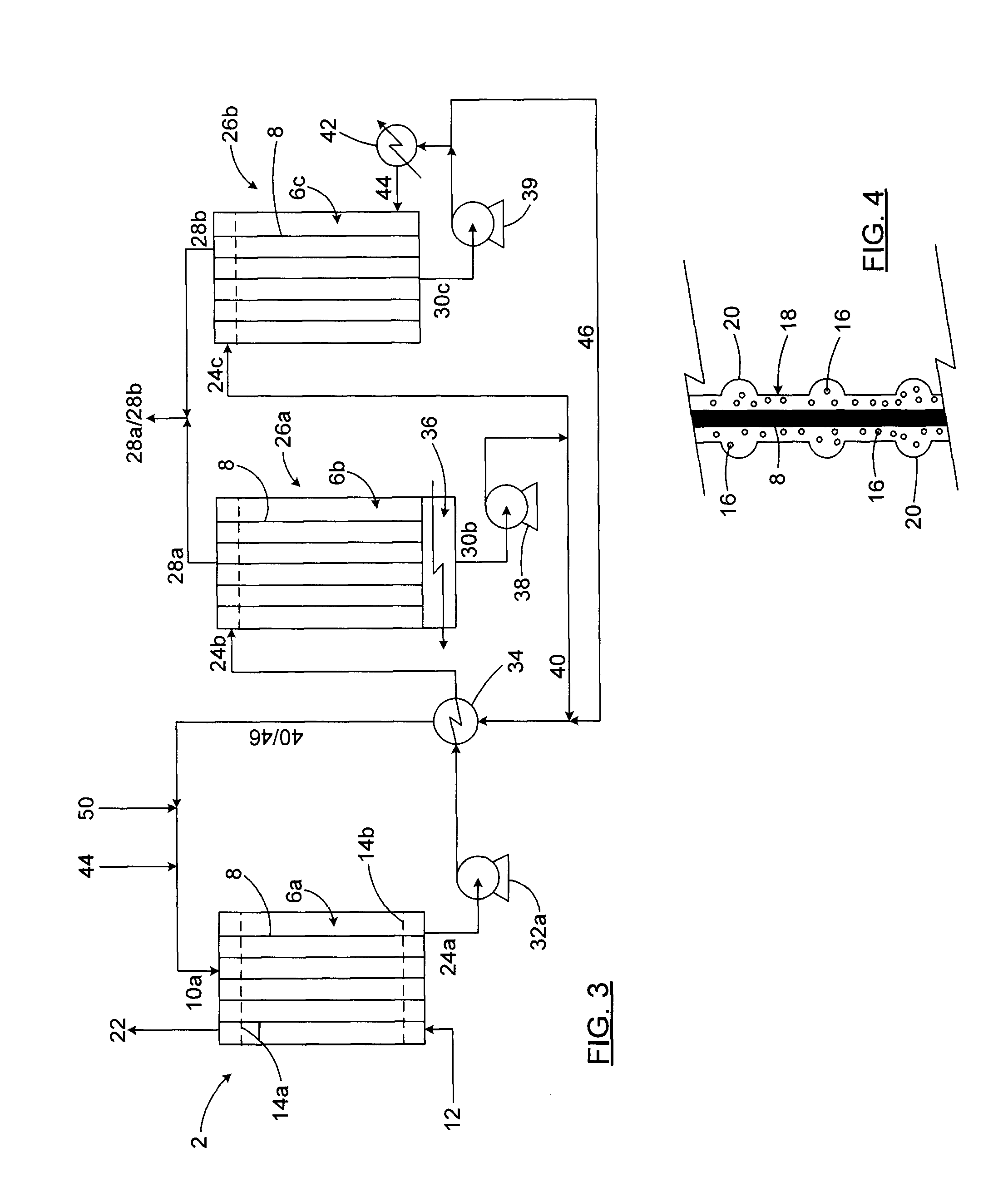
[0062]The present invention provides enzymatic processes and bioreactors for CO2 capture treatments, which use elongated structures to support flowing liquid layers comprising droplets to provide a flow regime for enhanced enzyme catalyzed reactions, e.g. reaction (I) as follows:

CO2+H2OHCO3−+H+  (I)

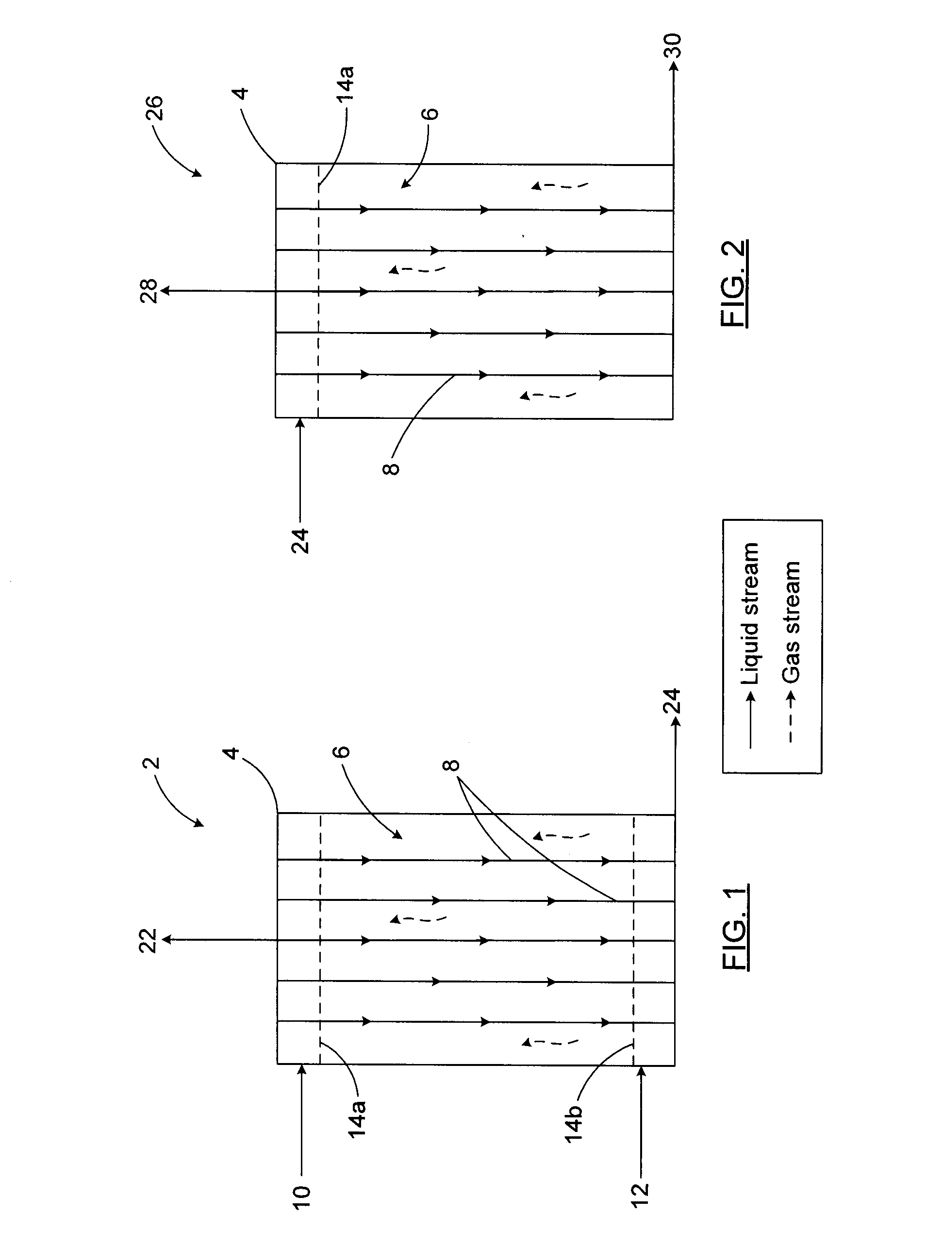
[0063]In one embodiment of the present invention shown on FIG. 1, the bioreactor is an absorption reactor (2). The absorption reactor (2) has a reaction chamber (4) which has a reaction zone (6) defined therein. There is also a plurality of elongated structures (8) within the reaction zone (6). The absorption reactor (2) also has a gas inlet and a liquid inlet. The absorption reactor (2) is fed with an absorption solution (10) and a CO2-containing gas (12). The gas (12) contacts the absorption solution (10) which flows down the elongated structures (8). The elongated structures (8) may be arranged vertically as shown in FIG. 1 or slightly inclined, preferably with their extremities mounte...


PUM

PropertyMeasurementUnit
chemicalaaaaaaaaaa
temperatureaaaaaaaaaa
mass transferaaaaaaaaaa

Abstract

An enzymatic process and bioreactor use elongated structures to enhance CO2 capture treatments. The enzymatic process and bioreactor treat a fluid by catalyzing reaction (I) with carbonic anhydrase, CO2+H2OHCO3+H+ (|) by feeding the fluid into a reaction zone wherein a plurality of elongated structures extend through the reaction zone. Each elongated structure supports a flowing liquid layer comprising droplets. Reaction (I) occurs within the flowing liquid layer in the presence of the carbonic anhydrase, to produce a gas stream and a liquid stream which are released. The process and bioreactor can be used in an absorption, desorption or combined treatment context.

Description

FIELD OF THE INVENTION[0001]The present invention generally relates to the field of CO2-containing gas treatment. More specifically, the invention relates to a process and a bioreactor using elongated structures to enhance CO2 capture treatments.BACKGROUND TO THE INVENTION[0002]Reduction of Green House Gases (GHG), such as CO2, is a challenging issue directly involving gas separation and capture processes. A very significant barrier to adoption of carbon capture technology on a large scale is cost of capture. The available technology for conventional CO2 capture is based primarily on the use of amine solvents within an absorption tower coupled to a desorption (or stripping) tower. This is an energy intensive process that involves heating the solvent to high temperature to strip the CO2 (and regenerate the solvent) for underground sequestration. The conventional use of amines involves an associated capture cost of approximately US $60 per ton of CO2 (IPCC), which represents approxima...

Claims


Application Information

Patent Timeline
Patent Type & Authority Applications(United States)
IPC IPC(8): C12M1/40C12S5/00
CPCB01D53/1475Y02C10/06B01D53/18B01D53/62B01D2251/606B01D2252/204B01D2252/20478B01D2252/20494B01D2252/602B01D2255/804B01D2257/504C12M21/18C12M29/00C12P3/00Y02C10/04B01D53/1493Y02P20/59Y02C20/40Y02P20/151
Inventor FRADETTE, SYLVIEBELZIL, ANNEDION, MELANIEPARENT, ROMAIN
Owner CO2 SOLUTION
Why Eureka
Try Eureka