
Universal power socket adaptor

a technology of universal sockets and adapters, applied in the direction of coupling contact members, two-part coupling devices, electrical appliances, etc., can solve the problems of troublesome travel and movement from one type of plug/socket arrangement to another, poor transfer of electricity, and inability to fit plugs of their appliances/devices into different shaped sockets, etc., to facilitate the insertion of pins and facilitate secure retention of springs

Inactive Publication Date: 2013-02-28
MA JESSE
View PDF9 Cites 1 Cited by
  • Summary
  • Abstract
  • Description
  • Claims
  • Application Information

AI Technical Summary

Benefits of technology

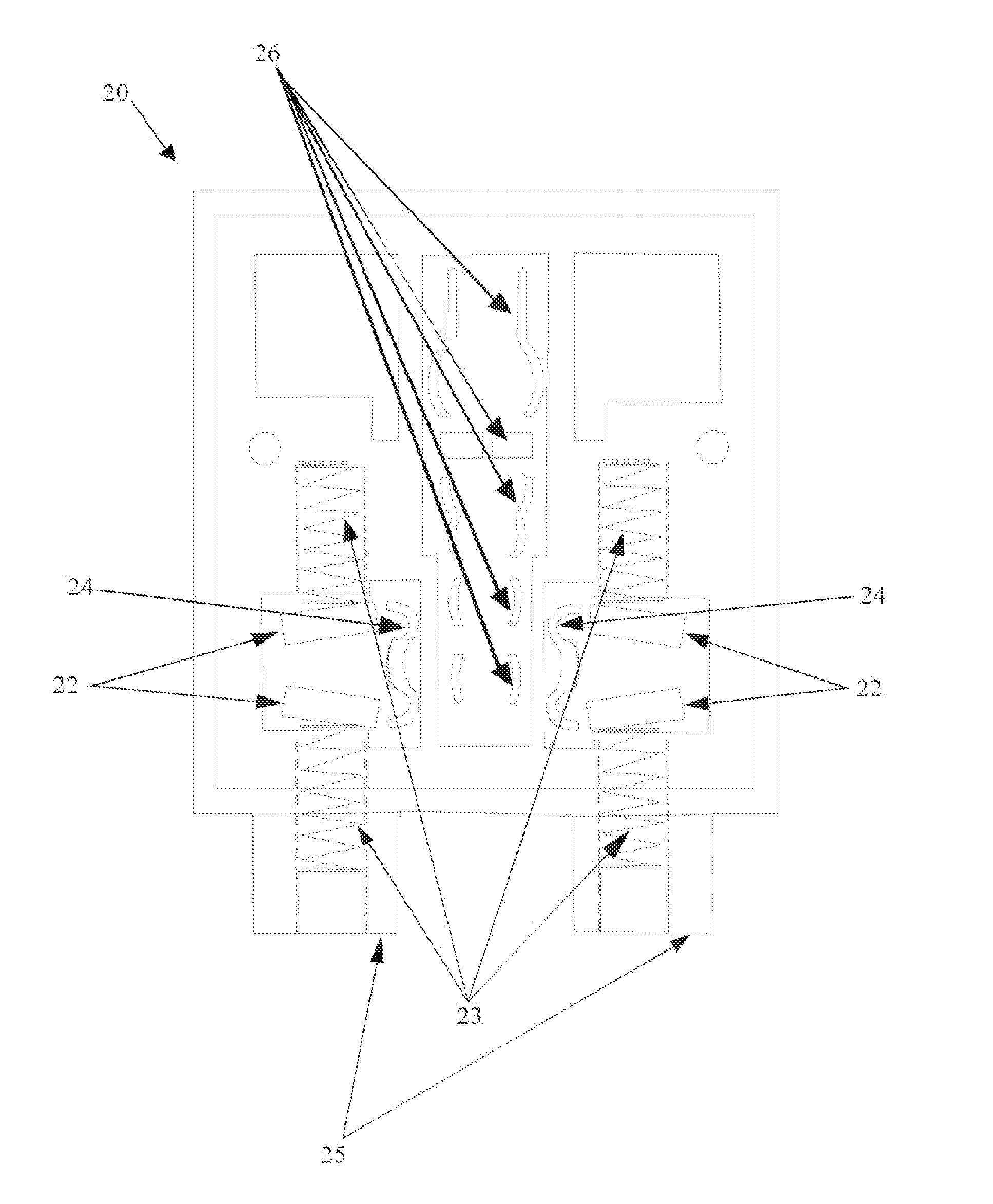
The patent is about a device that has a spring to help with electrical connections. The spring is held in place between a part of the device and the contact. It is designed to be secure and comfortable when the device is relaxed or when it is being used. The device also has openings and contacts that are shaped to make it easy to insert a pin and have it make good contact with the device.

Problems solved by technology

The differences in pin number, shape, and configuration makes travelling and moving from one type of plug / socket arrangement to another troublesome.
When a person travels or moves from that country / region to one with a different type of plug / socket arrangement, the plugs of their appliances / devices will not fit in to the different shaped sockets.
However, the bent pins typically do not make a very secure electrical engagement with the electrical contacts in the socket, which may mean that electricity is either poorly transferred, not transferred, or that arcing may occur (e.g. if there is an air gap between the pin and the contact).
Furthermore, because the pins are bent the plug will likely not fit completely into the socket meaning that portions of the pins where the bend is effected (e.g. twisted) will be exposed.
This is an electrocution hazard for anyone near the plug, or could also be a fire or short circuit hazard.
Additionally, the bending of the pins may damage the pins, particularly if they are bent too many times.
Although this may provide a safe and secure engagement with the socket, disadvantageously this is a more permanent solution and it is not feasible to easily switch between different pin configurations such as, for example, when a person is travelling between many different countries / regions with different plug types.
Furthermore, the adapter of this form can only receive one plug type, and cannot facilitate the connection of different plug types into any given socket.
As the contacts bent back more permanently, they no longer provided a suitable safe electrical engagement with the smaller pin types.
Particularly, after the contacts had been bent back the smaller pin types would not electrically connect properly and, for example, may intermittently come in and out of electrical engagement.
This is not only prone to arcing, which can cause fires or the like, but also can produce electromagnetic interference.
Furthermore, if the plug is not engaged securely, the plug may wobble or, worse, fall out of the socket.
Due to these shortcomings, sockets that allow multiple types of plug therein are generally not accepted for everyday or industrial use.
Accordingly, even in areas where it would be highly desirable to allow multiple plug types to be connected, for example in an airport or hotel, the universal sockets are generally not considered safe (e.g. don't meet the requisite electrical standards), and therefore only sockets of the particular country / region are utilised and it is up to the user of different plug types to provide their own, possibly unsafe, adapter to interface between their plug type and the socket of another.

Method used


Image

  • Universal power socket adaptor
  • Universal power socket adaptor
  • Universal power socket adaptor

Examples


Embodiment Construction

)

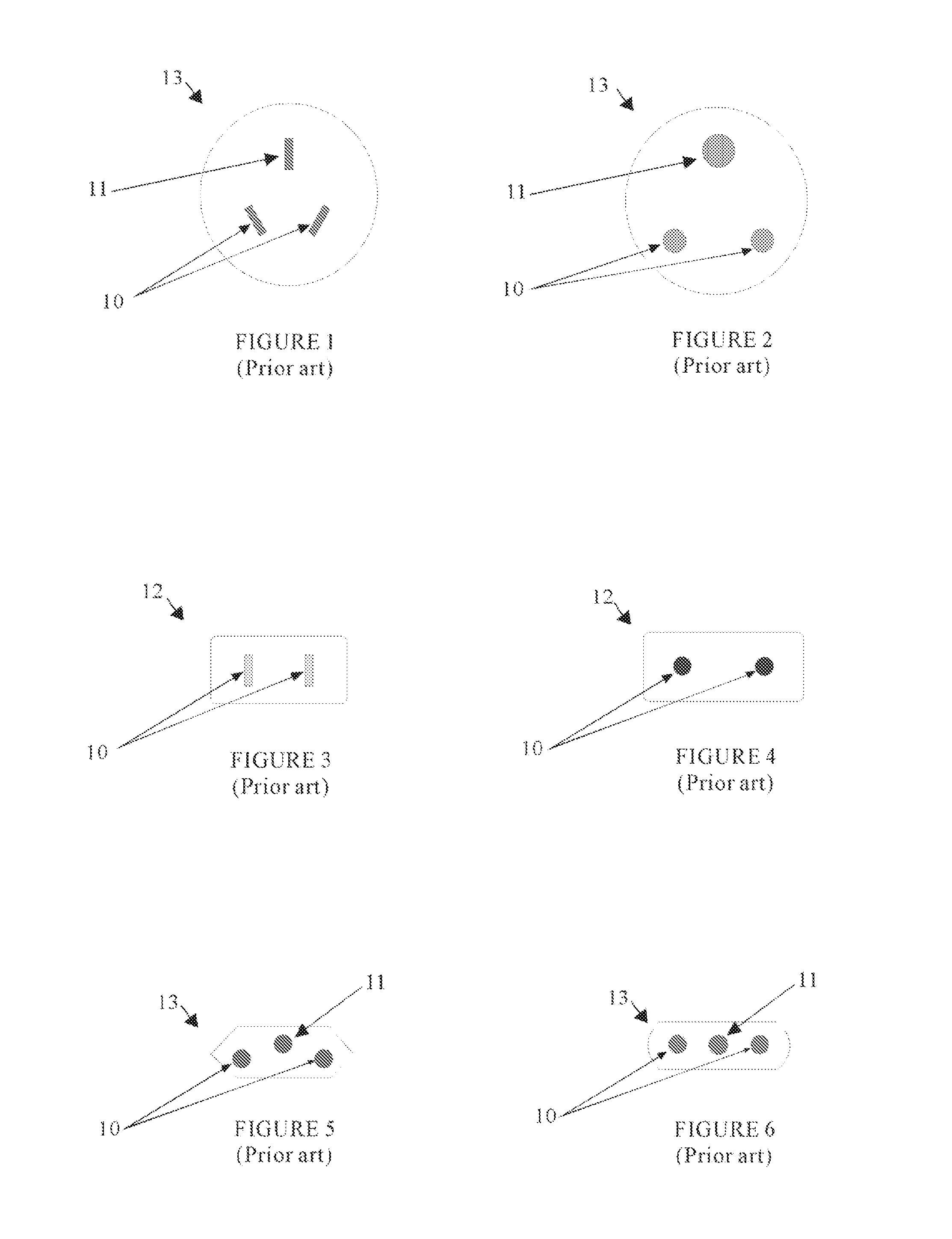
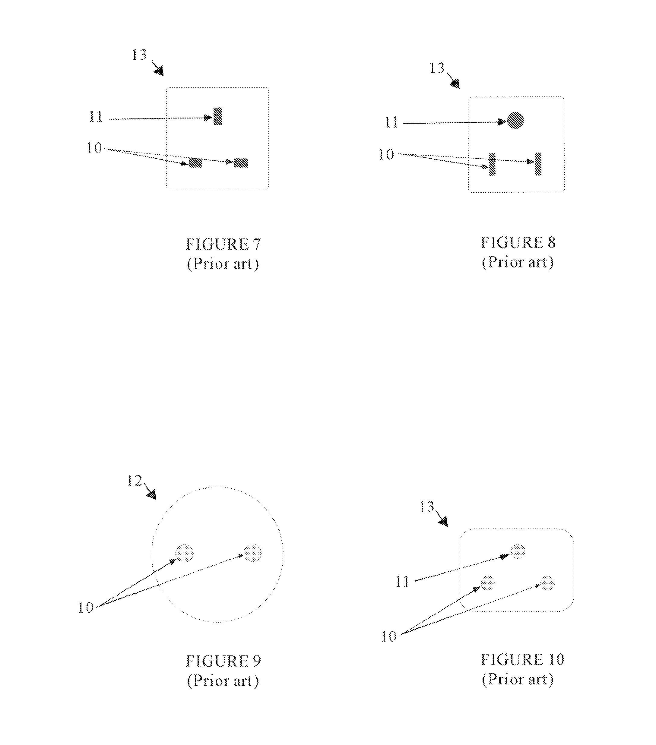
[0039]FIGS. 1 to 10 illustrate various pin configurations for power plugs utilised in different countries and regions around the world. Some of the configurations are for two pin plugs 12, such as illustrated in FIGS. 3, 4 and FIG. 9; and some of the configurations are for three pin plugs 13, such as illustrated in FIGS. 1, 2, 5 to 8, and 10. In the two pin plugs configurations, one of the pins is normally ‘active’ or ‘live’ and the other a ‘neutral’ or ‘return’. Essentially the live contact carries current from the source to the load and the neutral returns current to the source.

[0040]As the power supply is typically alternating current (AC), the polarity of the two active / natural pings 10 is often not considered essential. Accordingly, the illustrated two pin power plugs 12 (see FIGS. 3, 4, and 9) can be inserted into a corresponding socket in two different ways. In three pin plugs 13, the third pin is typically an ‘earth’ or ‘ground’ pin 11. The ground pin provides additional sa...


PUM


Abstract

The invention relates to power sockets and, more particularly, relates to universal power sockets capable of receiving, and electrically engaging with, different types of plugs having pins. Even more particularly, the invention relates to a universal power socket having sprung contacts. There are universal adapters already in existence, however some are unable to connect accurate and stably with a plug. Some may require a different pin clasp to hold it in place, whereas some adapters may be too big, or are not cost effective, and will still be unable to hold a vast range of power plugs. My invention has resolved all of these problems, something which has never previously been done. The creation of my universal adapter has enabled the use of only one clasp in order to hold 9 different pins. It is accurate and will hold power plugs stably in place, with the convenience of being able to connect to a majority of power plugs worldwide. My invention has safely adapted the power plug to be much smaller and convenient with the ease of having a low cost. It can be used for travel as a power adapter, as well as being used as an indoor power socket. The ability to be implanted indoors is beneficial to airports and hotels, where it will be of convenience for their customers who have arrived from a different country.

Description

BACKGROUND ART[0001][Mere reference to background art herein should not be construed as an admission that such art constitutes common general knowledge in relation to the invention.][0002]Since the adoption of electricity, in particular distributed electricity, buildings and houses have been fitted with electrical sockets in which electrical plugs, with pins thereon, can electrically engage with. The electrical socket typically has a switch and provides a point at which appliances and devices and the like can be plugged in to. Typically the socket is ‘female’ and the plug with pins is ‘male, with the pins at least comprising a portion of an electrically conductive material (e.g. a suitable metal).[0003]Over time, sockets, in particular wall sockets, developed, some including various features, usually safety features. Different countries and regions developed different power systems and standards, and also different plug / socket combinations. As far as the plug / socket is concerned, th...

Claims


Application Information

Patent Timeline
Patent Type & Authority Applications(United States)
IPC IPC(8): H01R13/11
CPCH01R24/22H01R2103/00H01R27/00
Inventor MA, JESSE
Owner MA JESSE
Learn More