Distribution design for fast raid rebuild architecture

a technology of distributed design and fast raid, applied in the field of storage systems, can solve the problems of reducing availability/reliability, storage sets the limitation of the distribution, etc., and achieves the effect of reducing availability/reliability, avoiding deterioration of availability/reliability, and total disk throughput performan

Inactive Publication Date: 2013-02-28
HITACHI LTD
View PDF9 Cites 15 Cited by
  • Summary
  • Abstract
  • Description
  • Claims
  • Application Information

AI Technical Summary

Benefits of technology

[0006]Exemplary embodiments of the invention provide a distribution design for fast RAID rebuild architecture that avoids the deterioration of the availability/reliability in the distribution architecture. The storage sets the limitation of the distribution. For example, the total disk throughput performance is slower than the other bandwidths, such as network bandwidth and processor bandwidth. The storage knows the configuration and performance of each of the components. The storage ca

Problems solved by technology

The storage sets the limitation of the distribution.
In this way, the distributed RAID architecture reduces the availab

Method used


Image

  • Distribution design for fast raid rebuild architecture
  • Distribution design for fast raid rebuild architecture
  • Distribution design for fast raid rebuild architecture

Examples


first embodiment

[0036]The first embodiment of this invention is based on the second embodiment of U.S. Pat. No. 7,904,749, which is incorporated herein by reference in its entirety. In this embodiment, the RAID level is 5, but it can be applied to RAID 6 and RAID 4 in a similar way.

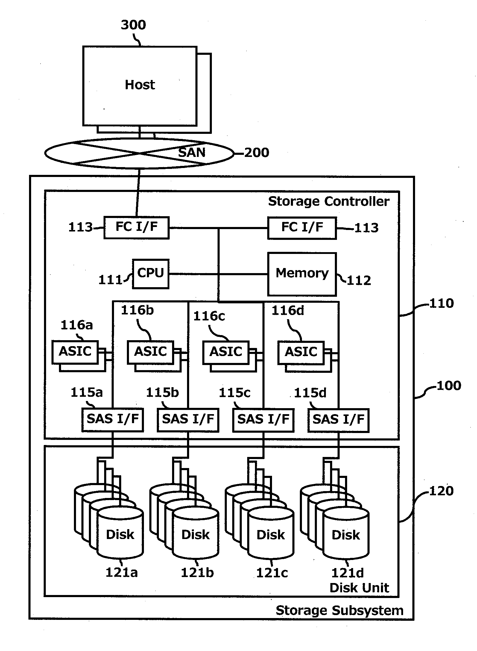
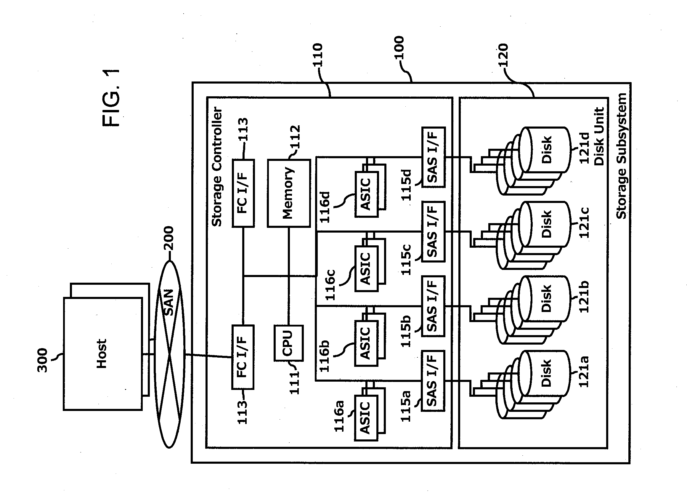
[0037]FIG. 1 illustrates an example of a hardware configuration of an information system in which the method and apparatus of the invention may be applied. A storage subsystem 100 is connected via a SAN (storage area network) to host computers 300. The storage subsystem 100 includes a storage controller 110 and a disk unit 120. The storage controller 110 has a CPU 111 that controls the storage subsystem 100 and runs the programs and uses the tables stored in a memory 112. The memory 112 stores data in addition to programs and tables. A channel interface 113 is provided for interfacing with the SAN 200. The storage controller 110 includes disk interfaces 115a to 115d that are linked to disks 121a to 121d in the disk unit ...

second embodiment

[0048]The second embodiment is based on the first embodiment. The following will focus on the differences between the two embodiments.

[0049]FIG. 9 illustrates an example of a memory 112 in the storage subsystem 100 of FIG. 1 according to the second embodiment. Only changes from the first embodiment of FIG. 4 will be discussed. In FIG. 9, a Page Rebuild Control 112-25-4′ (FIG. 10) is provided in place of the Page Rebuild Control 112-25-4 of FIG. 4 for the rebuild data in a parcel of broken disk.

[0050]FIG. 10 illustrates an example of a process flow of the Page Rebuild Control 112-25-4′ in the memory 112 of FIG. 9. This program runs when disk failure occurs. The program starts at 112-25-4-1. In step 112-25-4′-2, the program repeats this process until no parcel that belongs to the broken disk remains (i.e., all chunks in the broken RAID group are migrated). In step 112-25-4′-3, the program selects an unrecovered parcel of a broken disk, refers to the Capacity Pool Chunk Management Tabl...

third embodiment

[0052]The third embodiment is based on the second embodiment. The following will focus on the differences between the two embodiments. In this embodiment, the RAID level is 10, but it can be applied to RAID 1 in a similar way.

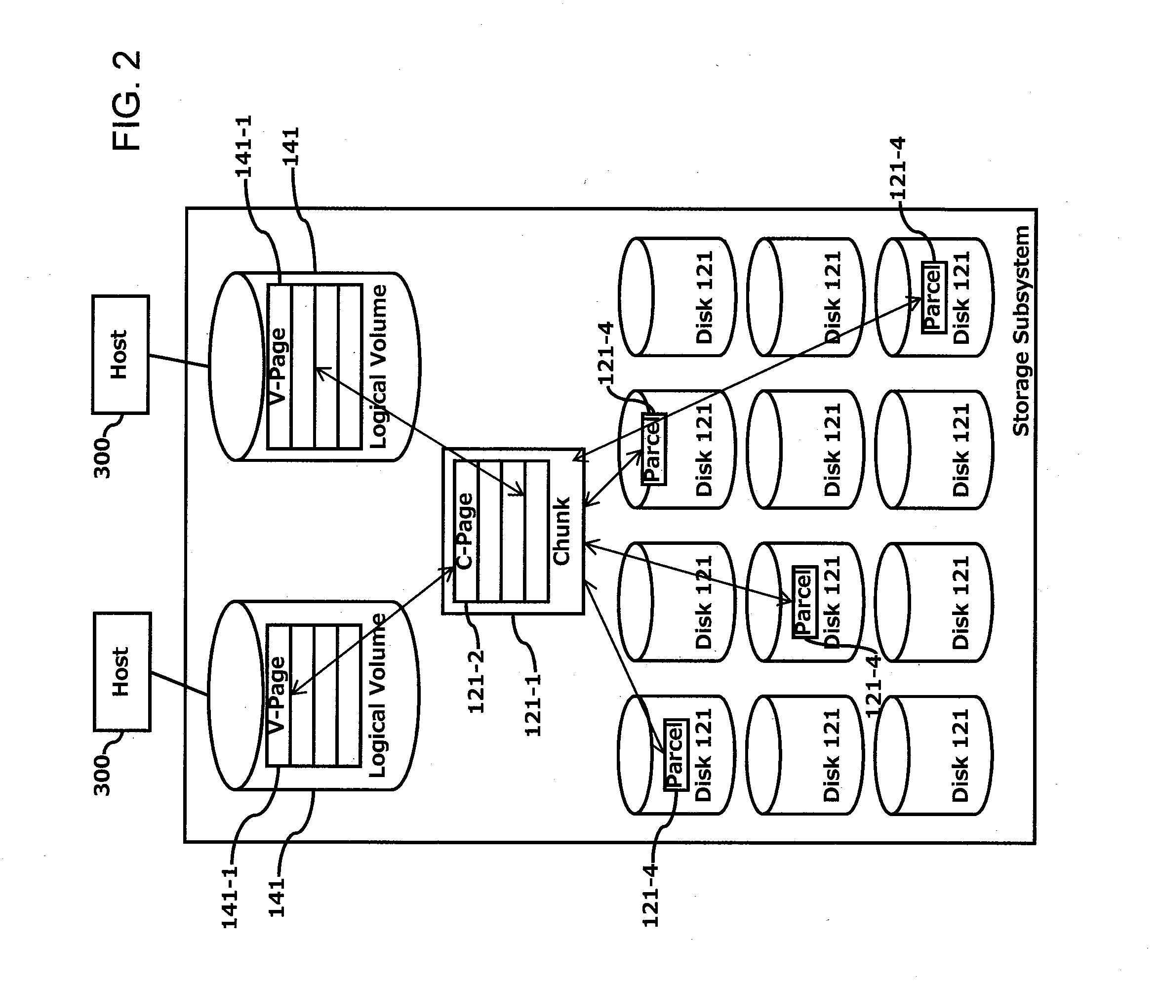
[0053]FIG. 12 illustrates an example of the logical configuration of a chunk 121-1 according to the third embodiment. Each disk is divided into plural parcels 121-4. Each parcel 121-4 is divided into plural capacity pool stripes 121-3. Four parcels 121-4 make up a chunk 121-1. Each of the four parcels 121-4 in a chunk 121-1 belongs to one disk 121 connected to different disk interfaces 115a-115d to avoid two points of failure. The selection of these four parcels 121-4 follows the evenly distributed algorithm. Each chunk 121-1 has plural capacity pool stripes 121-3 that make up a redundant array. In a stripe column in a chunk are data and mirrored data (as opposed to parity data in the first embodiment shown in FIG. 3).

[0054]FIG. 13 illustrates an example of the...


PUM


Abstract

Exemplary embodiments of the invention provide a distribution design for fast RAID rebuild architecture that avoids the deterioration of the availability/reliability in the distribution architecture. According to one aspect of the invention, a storage system comprises: a data storage unit including a plurality of storage devices; a storage controller including a processor, a memory, and a controller for controlling data transfer between the memory and corresponding storage devices in the data storage unit; and an internal network coupled between the storage controller and the storage devices. Based on loads of the processor of the storage controller and the internal network, the storage controller controls to limit a number of redundant storage devices over which to distribute a write data.

Description

BACKGROUND OF THE INVENTION[0001]The present invention relates generally to storage systems and, more particularly, to a distribution design for fast RAID rebuild architecture.[0002]Currently, storage has a data distribution architecture. See, e.g., U.S. Pat. No. 7,904,749 (based on RAID5 and RAID6) (hereinafter U.S. Pat. No. 7,904,749) and U.S. Patent Application Publication No. 2007 / 0174671 (based on RAID1) (hereinafter US 2007 / 0174671). Those systems distribute data to a pool which consists of multiple disks. When rebuild occurs by disk failure, the rebuild process also distributes to the entire pool. Those systems can make the rebuild process run in parallel, thereby shortening the rebuild time. For a disclosure on rebuilding a storage system, see, e.g., U.S. Patent Application Publication No. 2008 / 0091741.[0003]The storage reliability of a system can be calculated using the Markov model. For a traditional system based on RAID1 / RAID5, the formula to calculate the availability / re...

Claims


Application Information

Patent Timeline
IPC IPC(8): G06F12/00
CPCG06F2211/1059G06F11/1092G06F2211/1057
Inventor KAWAGUCHI, TOMOHIRO
Owner HITACHI LTD
Why Eureka
Try Eureka