Material testing system

Active Publication Date: 2013-03-07
SHIMADZU CORP
View PDF8 Cites 9 Cited by
  • Summary
  • Abstract
  • Description
  • Claims
  • Application Information

AI Technical Summary

Benefits of technology

[0023]According to the inventions according to the first to sixth aspects, on the basis of the successively computed change ratio R, the feedback control is performed, and therefore adequate material testing can be constantly performed. At this time, by reducing a variation in test force in the plastic region, the influence of noise can be prevented to obtain an adequate test result.
[0024]Accor

Problems solved by technology

In a material testing system using such a motor as a driving source, unless the above-described proportional gain, derivative gain, and integral gain are adequately set, accurate material testing that correctly follows a target value cannot be performed.
However,

Method used


Image

  • Material testing system
  • Material testing system
  • Material testing system

Examples


Example

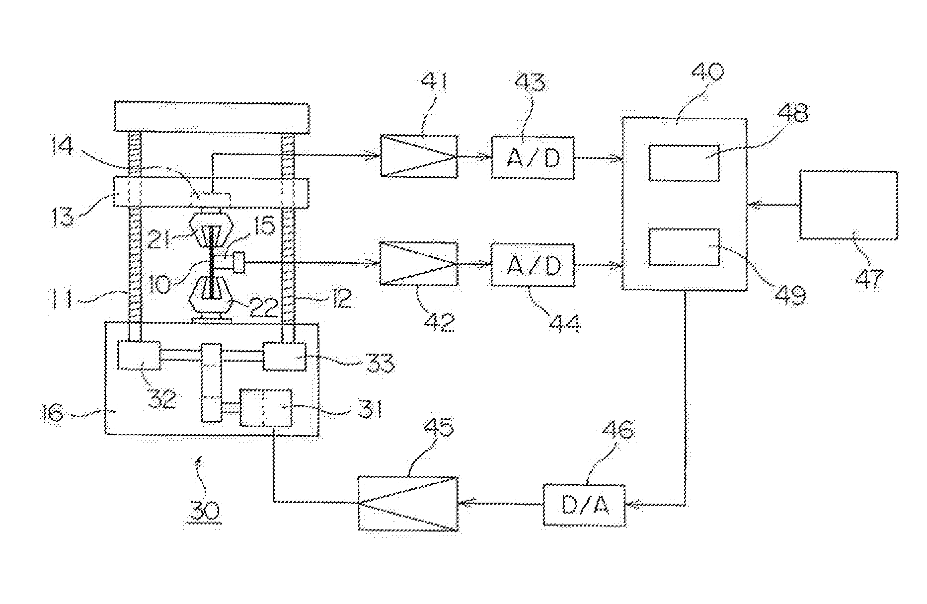
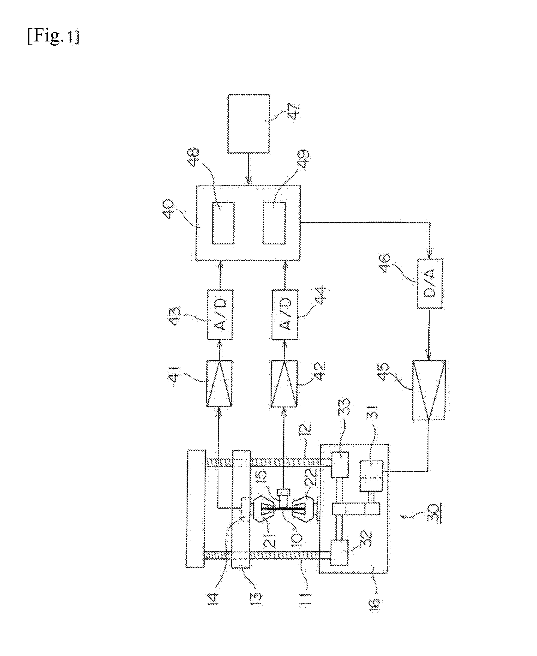
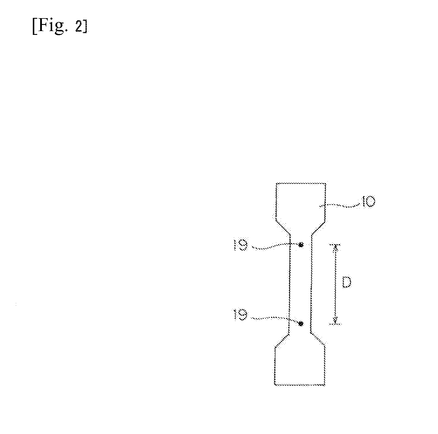
[0028]Embodiments of the present invention will hereinafter be described on the basis of the drawings. FIG. 1 is an outline diagram of a material testing system according to the present invention. In the outline diagram, a schematic diagram representing a mechanical configuration and a block diagram representing an electrical configuration are illustrated together. Also, FIG. 2 is an outline diagram of a test piece 10.

[0029]The material testing system is provided with: a table 16; a pair of screw rods 11 and 12 that is rotatably provided upright on the table 16 with facing in a vertical direction; a crosshead 13 that is movable along the screw rods 11 and 12; and a load mechanism 30 that is intended to move the crosshead 13 to apply a load to the test piece 10.

[0030]The crosshead 13 is connected to the pair of screw rods 11 and 12 through unillustrated nuts. Lower end parts of the respective screw rods 11 and 12 are connected with worm reducers 32 and 33 in the load mechanism 30, re...


PUM


Abstract

Provided is a material testing system that can prevent the influence of noise to obtain an adequate test result by reducing a variation in test force in a plastic region.
The material testing system is provided with: a displacement meter 15 that measures a displacement in distance between gage marks on a test piece 10; measuring means adapted to measure a displacement in rotational angle of a servo motor 31 that moves a crosshead 13; a computing part 48 that successively computes a change ratio R that is a ratio between the displacement in distance and the displacement in rotational angle; and a feedback control part 49 that, on the basis of the change ration R, performs feedback control of the servo motor 31, wherein when the change ratio R exceeds a setting value, a value of a parameter K used for the feedback control is changed to a value that makes the influence of the feedback control small.

Description

TECHNICAL FIELD[0001]The present invention relates to a material testing system, and in particular, to a material testing system that performs testing on a test piece having an elastic region and a plastic region.BACKGROUND ART[0002]Such a material testing system has a configuration in which, for example, a pair of screw rods is supported on a table rotatably in synchronization with each other, and both end parts of a crosshead are supported by the screw rods through nuts. Also, by using rotation of a motor to rotate the pair of screw rods in synchronization with each other, the crosshead is moved along the pair of screw rods. The crosshead and the table are respectively connected with grippers. The material testing system is configured to, in a state where both ends of a test piece are gripped by the pair of grippers, move the crosshead to thereby apply a load to the test piece.[0003]In such a material testing system, as the motor for rotating the screw rods, a servomotor is typica...

Claims


Application Information

Patent Timeline
IPC IPC(8): G01N3/02
CPCG01N3/08G01N2203/0682G01N2203/0208G01N2203/0094
Inventor KAWANO, TOSHIYUKI
Owner SHIMADZU CORP
Why Eureka
Try Eureka