Swing type switching device including magnet and magnetoresistive element

Inactive Publication Date: 2009-08-06
ALPS ALPINE CO LTD
View PDF6 Cites 0 Cited by
  • Summary
  • Abstract
  • Description
  • Claims
  • Application Information

AI Technical Summary

Benefits of technology

[0010]In the swing type switching device having the above-described structure, when the permanent magnet is positioned at the neutral position in the non-operation state of the operation body, the direction of the magnetic field vectors of the permanent magnet passing through the forming surface where the magnetoresistive element is formed is substantially parallel to the forming surface and the vector components perpendicular to the forming surface where the magnetoresistive element is formed are very few. Accordingly, even when the permanent magnet has a normal magnetic force, it is possible to apply a strong magnetic field to the magnetoresistive element. Thus, it is possible to prevent the influence of magnetic noise in the non-operation state corresponding to the highest frequency of the positioning. Further, in the case where the above structure is employed, even when the permanent mag

Problems solved by technology

However, the swing type switching device of this type has a disadvantage in that it is difficult to maintain high reliability over a long period of time because dust and the like may adhere to the contacts or the contacts may become worn or oxidized.
Accordingly, there is a concern that the magnetic field of the permanent magnet 22 acting on the output of the magnetoresistive element may become undesirably weak.
Accordingly, in the

Method used


Image

  • Swing type switching device including magnet and magnetoresistive element
  • Swing type switching device including magnet and magnetoresistive element
  • Swing type switching device including magnet and magnetoresistive element

Examples


Embodiment Construction

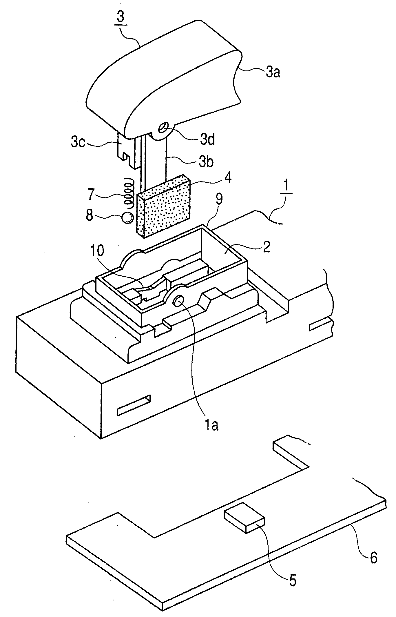
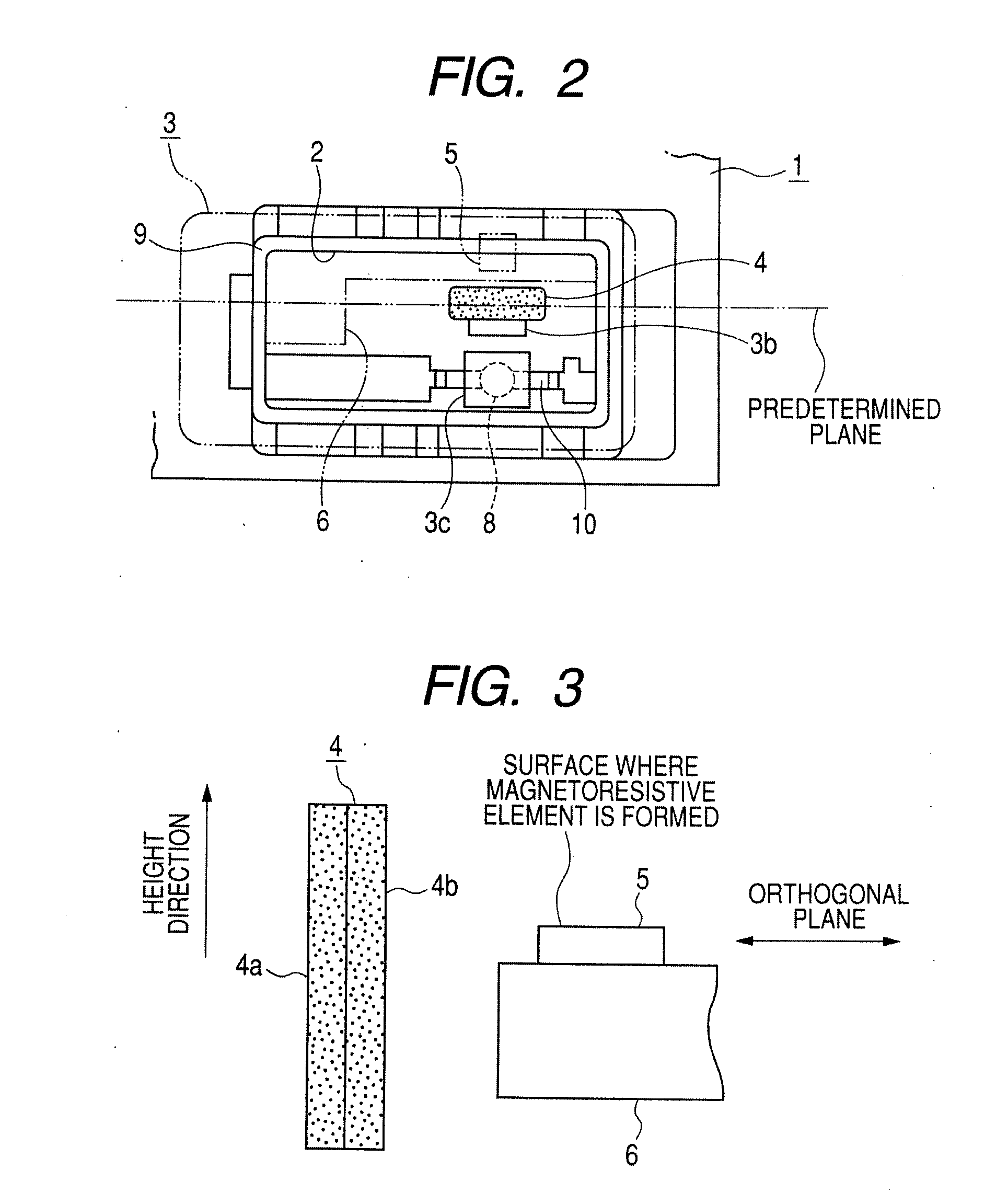
[0019]Embodiments of the invention will be described with reference to drawings. FIG. 1 is an exploded perspective view of a swing type switching device according to an embodiment of the invention. FIG. 2 is an explanatory diagram showing the inner structure of the switching device. FIG. 3 is an explanatory diagram showing a relative positional relationship between a permanent magnet and a GMR sensor of the embodiment. FIG. 4 is a characteristic diagram showing magnetic field vectors of the permanent magnet of the embodiment. FIG. 5 is an explanatory diagram showing a neutral position and a maximum displacement position of the permanent magnet of the embodiment. FIG. 6 is a circuit diagram of the GMR sensor of the embodiment. FIG. 7 is a characteristic diagram showing a relationship between the displacement of the permanent magnet and the output voltage of the GMR sensor of the embodiment.

[0020]A switching device shown in FIGS. 1 and 2 is a swing type switching device that uses a ma...


PUM


Abstract

A swing type switching device includes: an operation body that can swing and automatically returns to a neutral posture during a non-operation; a permanent magnet that moves along a predetermined plane by being interlocked with the operation body and is positioned at a neutral position during the non-operation of the operation body; and a magnetoresistive element of which the electrical resistance is changed in accordance with the change of a magnetic field that is caused by the movement of the permanent magnet. An operation position of the operation body can be detected on the basis of the change of the resistance of the magnetoresistive element, and the permanent magnet is magnetized so that pole faces thereof extend along the predetermined plane, and the magnetoresistive element is formed in a plane that is substantially orthogonal to a height direction of the permanent magnet positioned at the neutral position, and one pole face of the permanent magnet is close to and faces a side portion of the magnetoresistive element at the neutral position.

Description

CROSS REFERENCE TO RELATED APPLICATION [0001]The present invention contains subject matter related to and claims priority to Japanese Patent Application No. 2008-024043 filed in the Japanese Patent Office on Feb. 4, 2008, the entire contents of which being incorporated herein by reference.BACKGROUND[0002]1. Field of the Disclosure[0003]The present disclosure relates to a swing type switching device for performing a switching operation by the swing of an operation body, such as a switching device for a power window of a vehicle, and particularly to, a swing type switching device that uses a magnetism detecting method.[0004]2. Description of the Related Art[0005]Generally, a swing type switching device such as a switching device for a power window has a structure in which, if an operation body swings, a movable contact and a fixed contact come into contact with or separate from each other to perform the switching. However, the swing type switching device of this type has a disadvantag...

Claims


Application Information

Patent Timeline
IPC IPC(8): H03K17/94
CPCH03K17/9517
Inventor KIKUCHI, YUYA
Owner ALPS ALPINE CO LTD
Why Eureka
Try Eureka