Apparatus for inspecting edge of substrate

Active Publication Date: 2015-07-16
SAMSUNG CORNING PRECISION MATERIALS CO LTD
View PDF19 Cites 6 Cited by
  • Summary
  • Abstract
  • Description
  • Claims
  • Application Information

AI Technical Summary

Benefits of technology

[0018]According to the present invention, it is possible to obtain images from all of the upper surface, the lower surface and the end surface of an edge portion of a substrate using a single optical device.
[0019]In addition, according to the present invention, the images of the upper surface and the lower surface of the edge portion of the substrate are obtained from light incident onto the inclined surfac

Problems solved by technology

However, the inspection apparatus disclosed in Patent Document 1 has a drawback in that this apparatus must use a plurality of optical devices in order to inspect the upper surface, the lower surface and the end surface of t

Method used


Image

  • Apparatus for inspecting edge of substrate
  • Apparatus for inspecting edge of substrate
  • Apparatus for inspecting edge of substrate

Examples


Example

[0027]Reference will now be made in detail to exemplary embodiments of an apparatus for inspecting an edge portion of a substrate according to the present invention in conjunction with the accompanying drawings so that a person skilled in the art to which the present invention relates could easily put the present invention into practice.

[0028]Throughout this document, reference should be made to the drawings, in which the same reference numerals and symbols are used throughout the different drawings to designate the same or similar components. In the following description of the present invention, detailed descriptions of known functions and components incorporated herein will be omitted in the case that the subject matter of the present invention is rendered unclear.

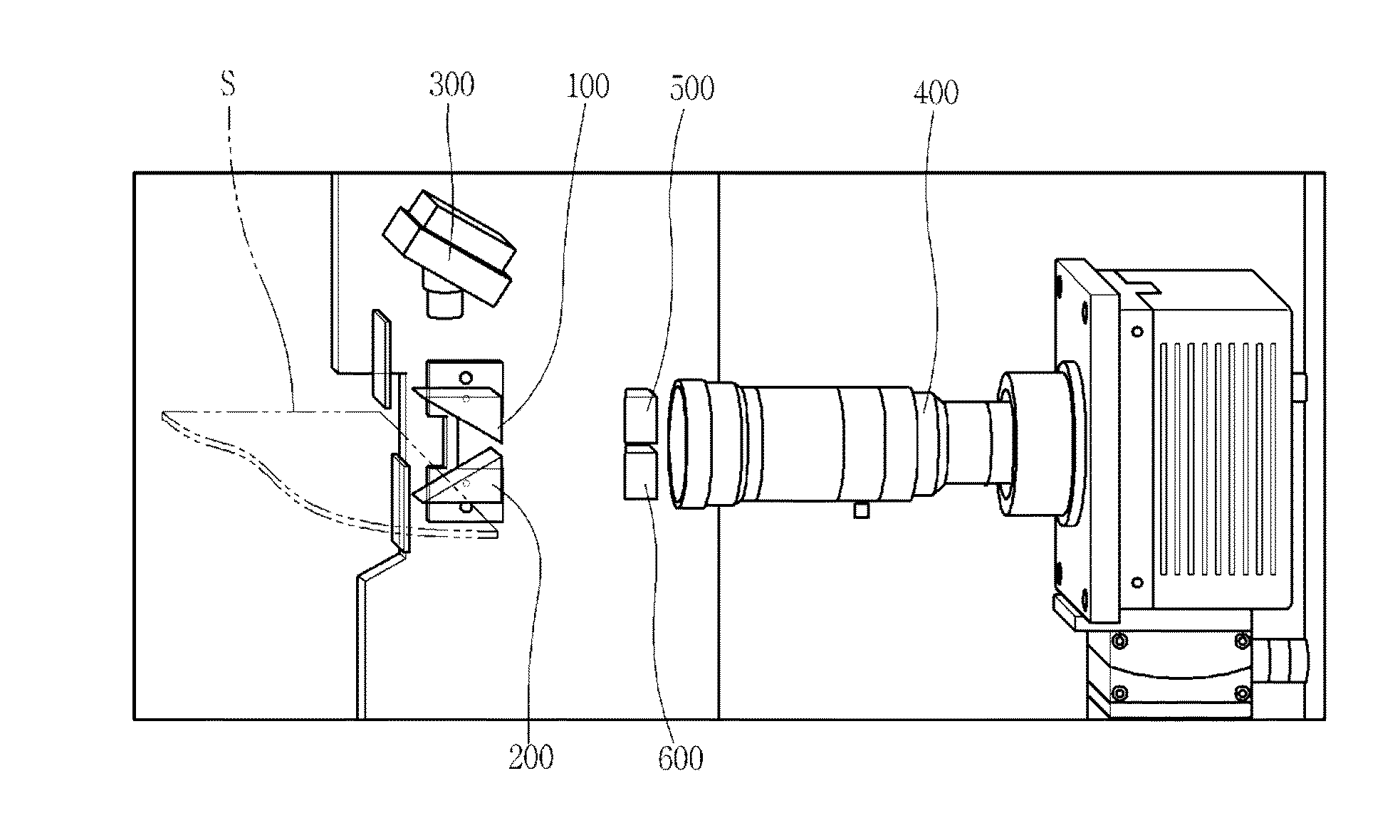
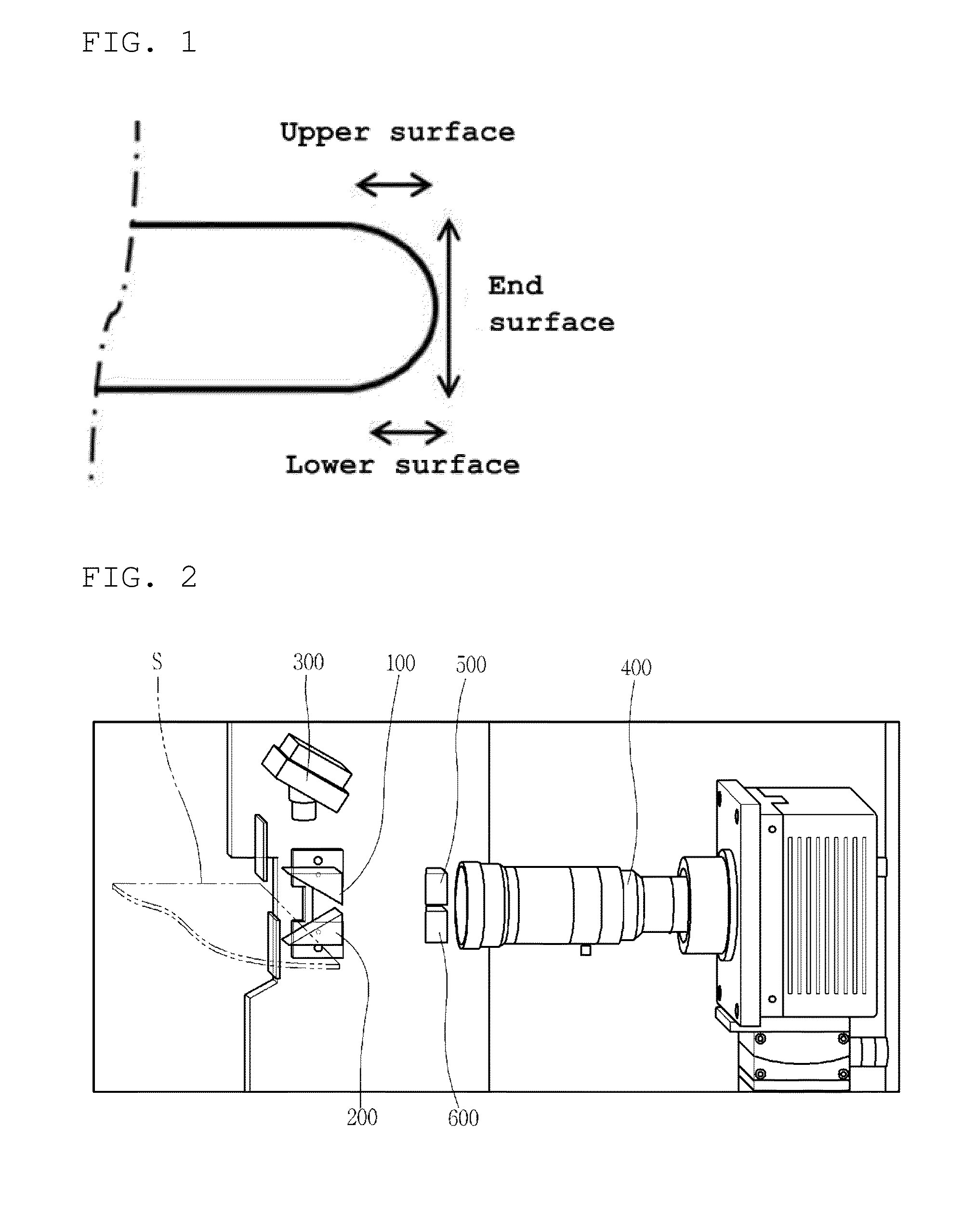
[0029]FIG. 2 is a schematic configuration view illustrating an apparatus for inspecting an edge portion of a substrate according to an exemplary embodiment of the present invention.

[0030]The apparatus for inspecting an ...


PUM


Abstract

An apparatus for inspecting an edge portion of a substrate can inspect a defect or a chamfered width on an edge portion of a substrate. First and second right-angled prisms are disposed above and below the edge portion such that inclined surfaces thereof are directed toward the upper surface and lower surface of the edge portion. A lighting part irradiates the edge portion of the substrate with light. A photographing part is disposed adjacent to the edge portion. The photographing part takes an image of the upper surface of the edge portion from light that has passed through the first right-angled prism, an image of the lower surface of the edge portion from light that has passed through the second right-angled prism, and an image of an end surface of the edge portion.

Description

BACKGROUND OF THE INVENTION[0001]1. Field of the Invention[0002]The present invention relates to an apparatus for inspecting an edge portion of a substrate, and more particularly, to an apparatus for inspecting an edge portion of a substrate able to inspect a defect or a chamfered width on an edge portion of a substrate.[0003]2. Description of Related Art[0004]A glass substrate used in flat panel displays, such as thin-film transistor liquid crystal displays (TFT-LCDs), plasma display panels (PDPs) and electroluminescent (EL) displays, is manufactured by a shaping process of shaping molten glass produced from a glass melting furnace into a flat glass plate and a cutting process of cutting the flat glass plate according to predetermined dimensions. The manufactured glass substrate is subsequently transported to a machining line, in which the glass substrate is in turn machined. In the machining line, the glass substrate is cut again according to the dimension of a flat panel display ...

Claims


Application Information

Patent Timeline
IPC IPC(8): G01N21/88H04N5/238H04N5/225H01L21/67G01N21/958
CPCG01N21/8851H01L21/67253G01N21/958G01N2201/105H04N5/238G01N2201/062H04N5/2256H01L21/67288G01N21/896G01N21/9503H04N23/56
Inventor SEONG, SIHO
Owner SAMSUNG CORNING PRECISION MATERIALS CO LTD
Why Eureka
Try Eureka