
Light-emitting diode lamp

Inactive Publication Date: 2013-03-07
SAMSUNG ELECTRONICS CO LTD
View PDF5 Cites 8 Cited by
  • Summary
  • Abstract
  • Description
  • Claims
  • Application Information

AI Technical Summary

Benefits of technology

The patent text describes a new structure for a light-emitting diode lamp that uses a non-insulation type power supply unit and has an improved heat radiation member. The heat radiation member includes a mounting unit and a cylindrical unit that surrounds the power supply unit to discharge heat generated by the light-emitting diode package. The heat radiation plastic is made of polyphenylene sulfide group material with a ceramic filler like alumina, MgO, BN, or AlN to improve its properties. The heat radiation member can be made of aluminum or produced by insert-injection molding. The light-emitting diode lamp also includes a socket unit, an insulating member, and a lamp cover. The non-insulation type power supply unit includes a transformation circuit without a transformer. This improved structure helps to better control the heat generated by the light-emitting diode package and to achieve better performance.

Problems solved by technology

However, as the output increases, it is not easy to secure a sufficient heat radiation characteristic within a limited size and type.

Method used


Image

  • Light-emitting diode lamp
  • Light-emitting diode lamp
  • Light-emitting diode lamp

Examples


Embodiment Construction

[0025]Reference will now be made in detail to exemplary embodiments, examples of which are illustrated in the accompanying drawings. In the drawings, thicknesses of layers or regions are exaggerated for clarity. Like reference numerals refer to like elements throughout and thus descriptions thereof will be omitted.

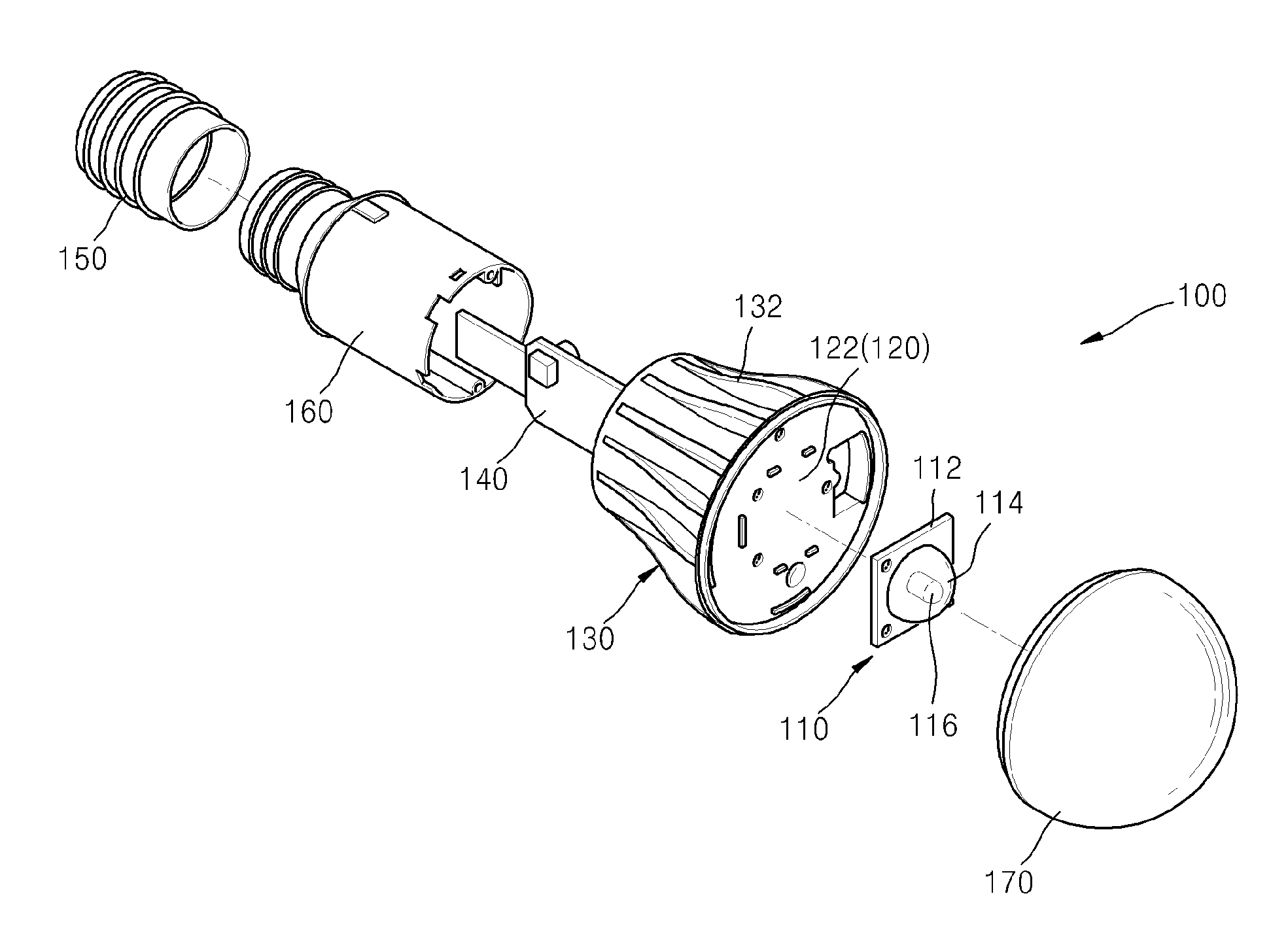
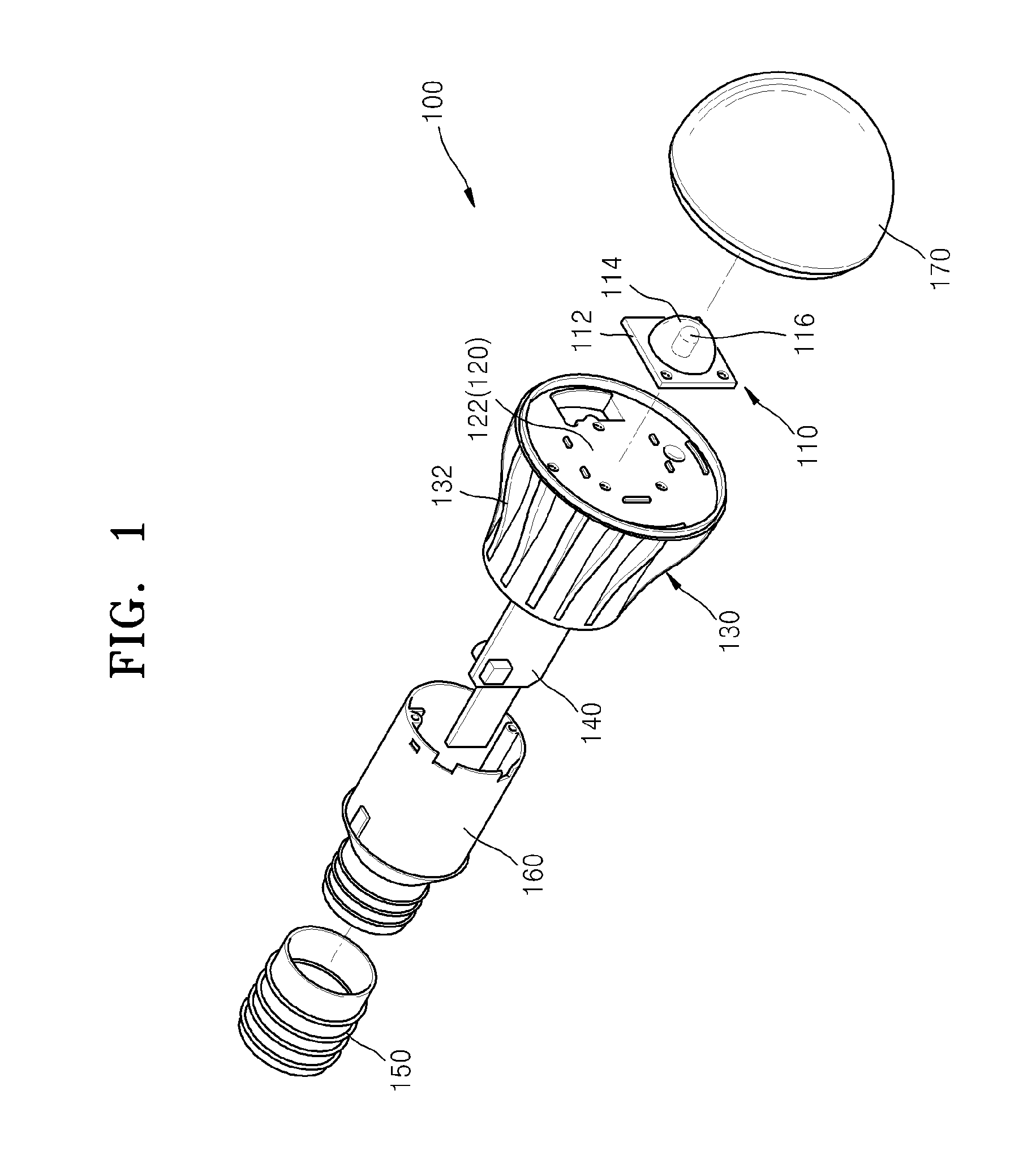
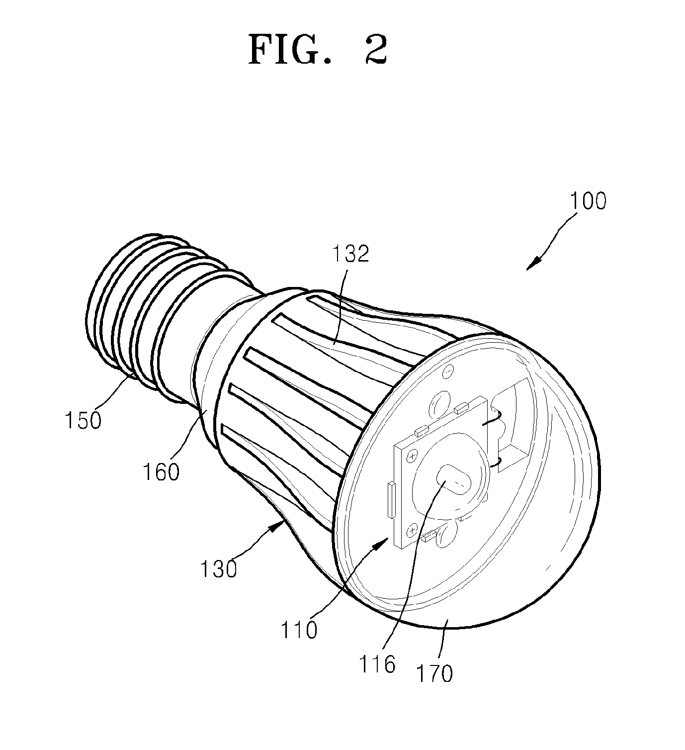
[0026]FIG. 1 is an exploded perspective view of a light-emitting diode lamp 100 according to an exemplary embodiment. FIG. 2 is a perspective view of the light-emitting diode lamp 100 according to an exemplary embodiment. The light-emitting diode lamp 100 depicted in FIGS. 1 and 2 is an incandescent lamp type.

[0027]Referring to FIGS. 1 and 2, the light-emitting diode lamp 100 includes a heat radiation member 120 that provides a mounting unit 122 on which a light-emitting diode package 110 is mounted, a power supply unit 140 that is surrounded by the heat radiation member 120 and supplies power to the light-emitting diode package 110, and a lamp cover 170.

[0028]The light-em...


PUM


Abstract

A light-emitting diode lamp is provided. The light-emitting diode lamp includes a light-emitting diode package that includes a light-emitting diode and a circuit substrate on which the light-emitting diode is mounted; a power supply unit that supplies power to the light-emitting diode; a heat radiation member that includes a mounting unit on which the light-emitting diode package is mounted and a cylindrical unit extending from the mounting unit and surrounding the power supply unit to discharge heat generated by the light-emitting diode package; and a heat radiation plastic that surrounds an outer surface of the cylindrical unit.

Description

CROSS-REFERENCE TO RELATED APPLICATION[0001]This application claims priority from Korean Patent Application No. 10-2011-0089209, filed on Sep. 2, 2011 in the Korean Intellectual Property Office, the disclosure of which is incorporated by reference herein in its entirety.BACKGROUND[0002]1. Field[0003]The present disclosure relates to light-emitting diode lamps, and more particularly, to small light-emitting diode lamps having a small non-insulation type power supply unit.[0004]2. Description of the Related Art[0005]Light-emitting diodes (LEDs) are semiconductor devices that realize various light colors by configuring a light source having a PN junction of compound semiconductors. LEDs have a long lifetime, may be miniaturized and may be driven at a low voltage due to high directionality. Also, LEDs are strong against impact and vibration, do not require a preheating time or a complicated driving arrangement, and may be packaged in various types. Accordingly, LEDs may be applied for v...

Claims


Application Information

Patent Timeline
IPC IPC(8): H01L33/64
CPCF21Y2101/02F21K9/1355F21V29/86F21V23/006F21V29/74F21V3/02F21K9/23F21Y2115/10F21K9/238F21V29/00
Inventor KIM, SUNG-JINSONG, BYUNG-KWAN
Owner SAMSUNG ELECTRONICS CO LTD
Features
  • Generate Ideas
  • Intellectual Property
  • Life Sciences
  • Materials
  • Tech Scout
  • Unparalleled Data Quality
  • Higher Quality Content
  • 60% Fewer Hallucinations
Learn More