Current sensor

a current sensor and current sensor technology, applied in the field of current sensors, can solve the problems of reducing the accuracy of current measurement, affecting the measurement accuracy of current sensors, and unable to sufficiently extend the current measurement range of current sensors, so as to reduce the external magnetic field and suppress the influence of hysteresis

Inactive Publication Date: 2013-03-07
ALPS GREEN DEVICES
View PDF8 Cites 21 Cited by
  • Summary
  • Abstract
  • Description
  • Claims
  • Application Information

AI Technical Summary

Benefits of technology

[0008]The present invention has been made in consideration of the above-described disadvantages. The present invention provides a c

Problems solved by technology

If an external magnetic field reduced by the shield is applied to the magnetic sensor, an output of the sensor will have hysteresis.
Disadvantageously, th

Method used


Image

  • Current sensor
  • Current sensor
  • Current sensor

Examples


Embodiment Construction

[0024]The inventor found that designing a current sensor including a magnetoresistive element and magnetic shields such that the magnetic shields include a first magnetic shield placed in a region covering the magnetoresistive element and a second magnetic shield placed near, or apart from the first magnetic shield reduces an external magnetic field while suppressing the influence of hysteresis of the magnetic shields. An embodiment of the present invention will be described in detail below with reference to the drawings.

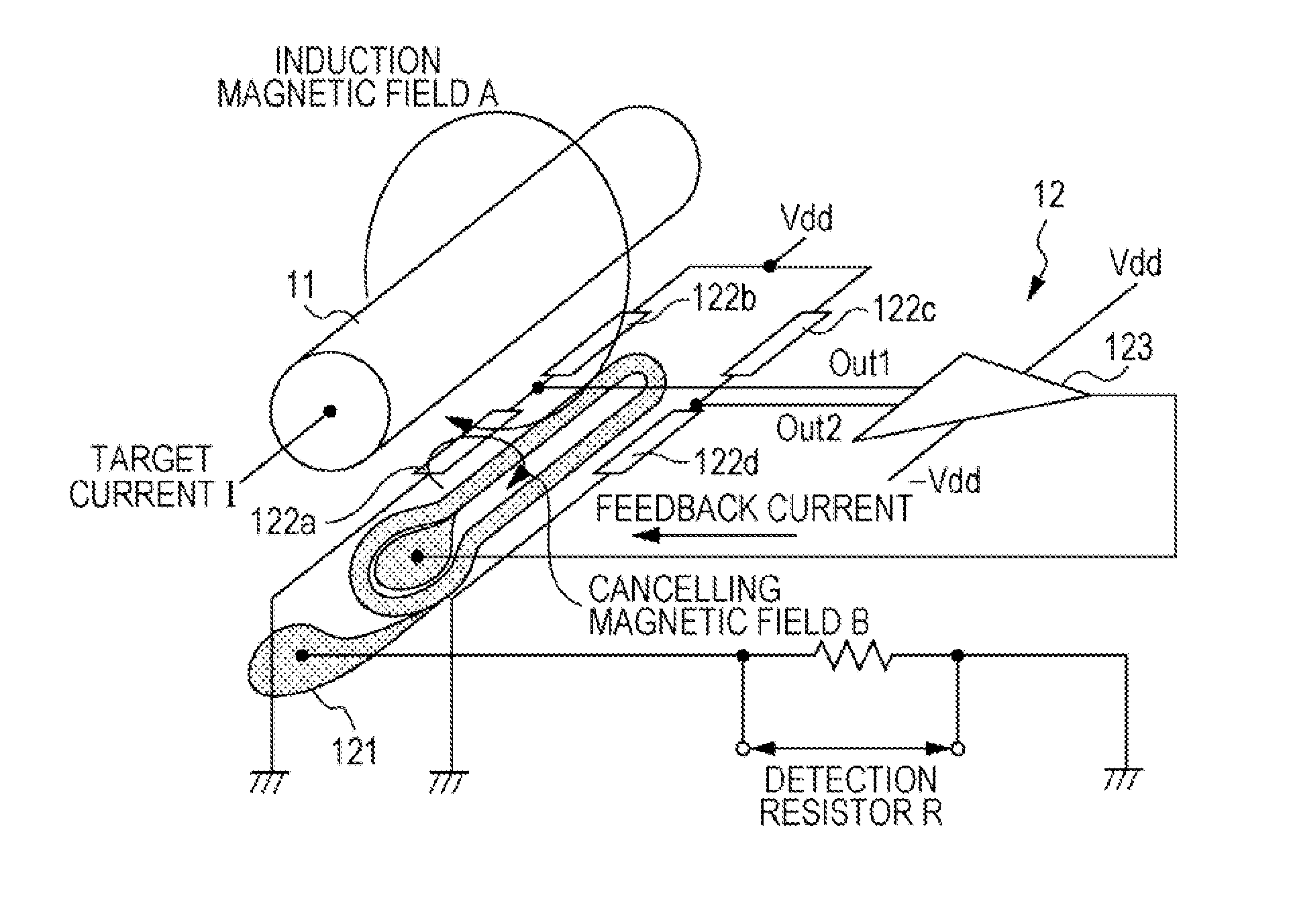
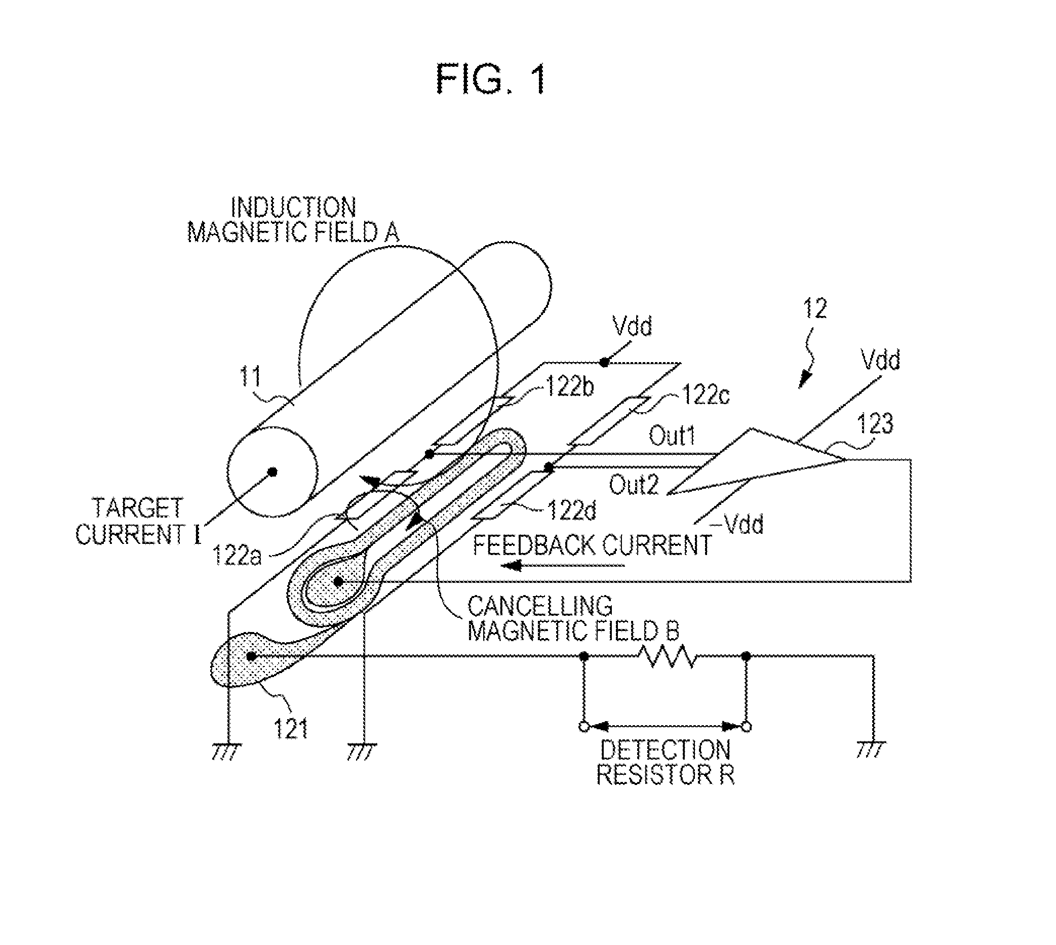
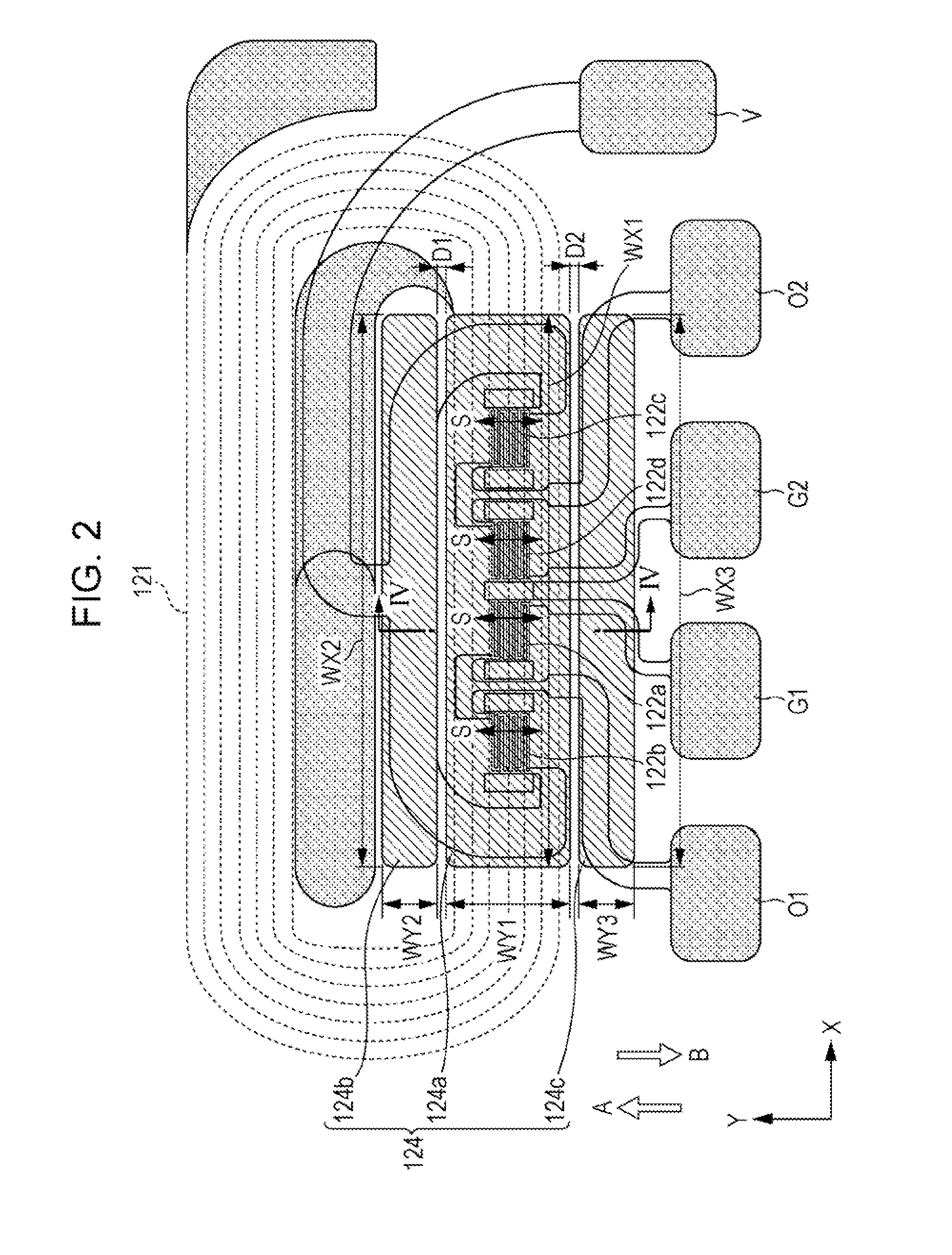
[0025]FIG. 1 is a schematic diagram of an exemplary structure of a magnetic balance current sensor according to the embodiment. FIG. 1 principally illustrates the connection relationship between magnetoresistive elements 122a to 122d constituting the magnetic balance current sensor. The specific structure of each element and the arrangement of the elements will be described in detail later with reference to FIG. 2 and subsequent figures. Referring to FIG. 1, the mag...


PUM


Abstract

A current sensor includes a magnetoresistive element and magnetic shields arranged between a current line and the magnetoresistive element. The magnetic shields include a flat first magnetic shield placed so as to attenuate the strength of an induction magnetic field applied to the magnetoresistive element and a flat second magnetic shield placed apart from the first magnetic shield in a direction in-plane with the main surface of the first magnetic shield so as to attenuate the strength of the induction magnetic field applied to the magnetoresistive element and reduce the influence of residual magnetization in the first magnetic shield.

Description

CLAIM OF PRIORITY[0001]This application claims benefit of Japanese Patent Application No. 2011-191592 filed on Sep. 2, 2011, which is hereby incorporated by reference.BACKGROUND OF THE INVENTION[0002]1. Field of the Invention[0003]The present invention relates to current sensors measuring current in a noncontact manner.[0004]2. Description of the Related Art[0005]In the field of motor drive technology for electric vehicles and hybrid cars, a relatively large current is used. Current sensors capable of measuring a large current in a noncontact manner are therefore demanded. Such a current sensor has been in practical use which detects a change in magnetic field, caused by a current to be measured (hereinafter, also referred to as a “target current”), using a magnetic sensor. Some current sensors of this type include a member that serves as a shield against an external magnetic field in order to reduce the external magnetic field applied to the magnetic sensor (refer to PCT Japanese T...

Claims


Application Information

Patent Timeline
IPC IPC(8): G01R33/09
CPCG01R33/093
Inventor IDE, YOSUKE
Owner ALPS GREEN DEVICES
Why Eureka
Try Eureka