Piezoelectric vibration device and oscillator

a technology of vibration device and oscillator, which is applied in the direction of oscillator, piezoelectric/electrostrictive/magnetostrictive device, piezoelectric/electrostrictive/magnetostriction machine, etc. it can solve the problems of changing the vibration characteristics, and achieve the effect of stably holding the piezoelectric vibrating reed and minimizing the adverse effect of the base substrate stress and strain

Inactive Publication Date: 2013-03-07
SII CRYSTAL TECH
View PDF10 Cites 7 Cited by
  • Summary
  • Abstract
  • Description
  • Claims
  • Application Information

AI Technical Summary

Benefits of technology

[0019]The present invention can minimize the adverse effect of the stress and strain of the base substrate on the piezoelectric vibrating reed. Specifically, because the distance between the metal bumps is shorter than in the method of related art used to hold the piezoelectric vibrating reed, the stress and strain exerted on the piezoelectric vibrator from the cover substrate or the base substrate do not fluctuate as much, and the characteristics of the piezoelectric vibrating reed can be stabilized. It is also possible to stably hold the piezoelectric vibrating reed.

Problems solved by technology

Such stress is problematic, because it is exerted on the piezoelectric vibrating reed, and greatly changes the vibration characteristics of the piezoelectric vibrating reed.

Method used


Image

  • Piezoelectric vibration device and oscillator
  • Piezoelectric vibration device and oscillator
  • Piezoelectric vibration device and oscillator

Examples


first embodiment

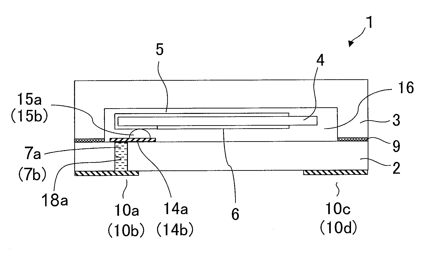
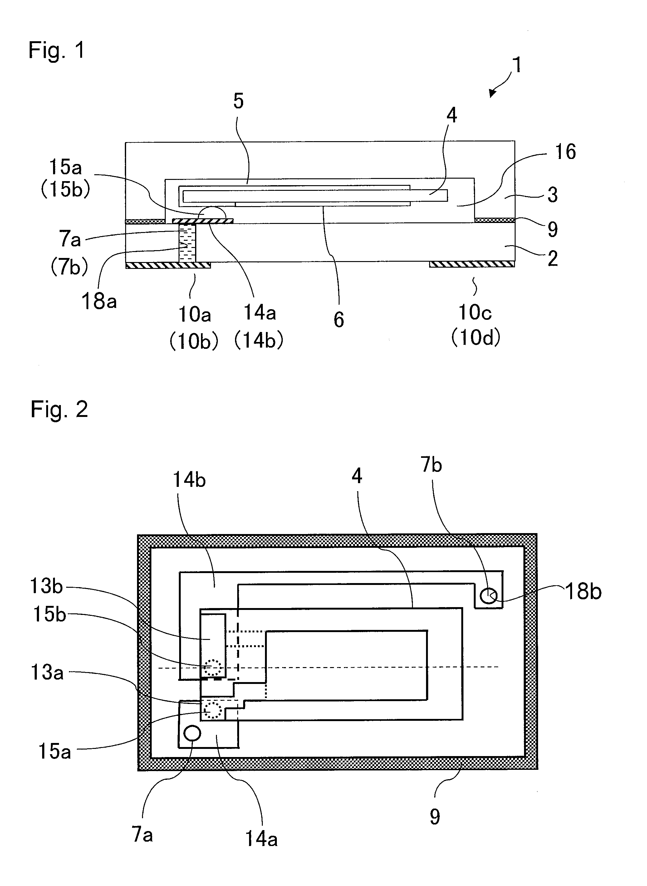
[0027]FIG. 1 is a cross sectional view of a piezoelectric vibration device 1 according to First Embodiment taken along the longer side through a through electrode 7a, as viewed from the side of a piezoelectric vibrating reed 4. FIG. 2 is a schematic view showing a top surface of the piezoelectric vibration device 1.

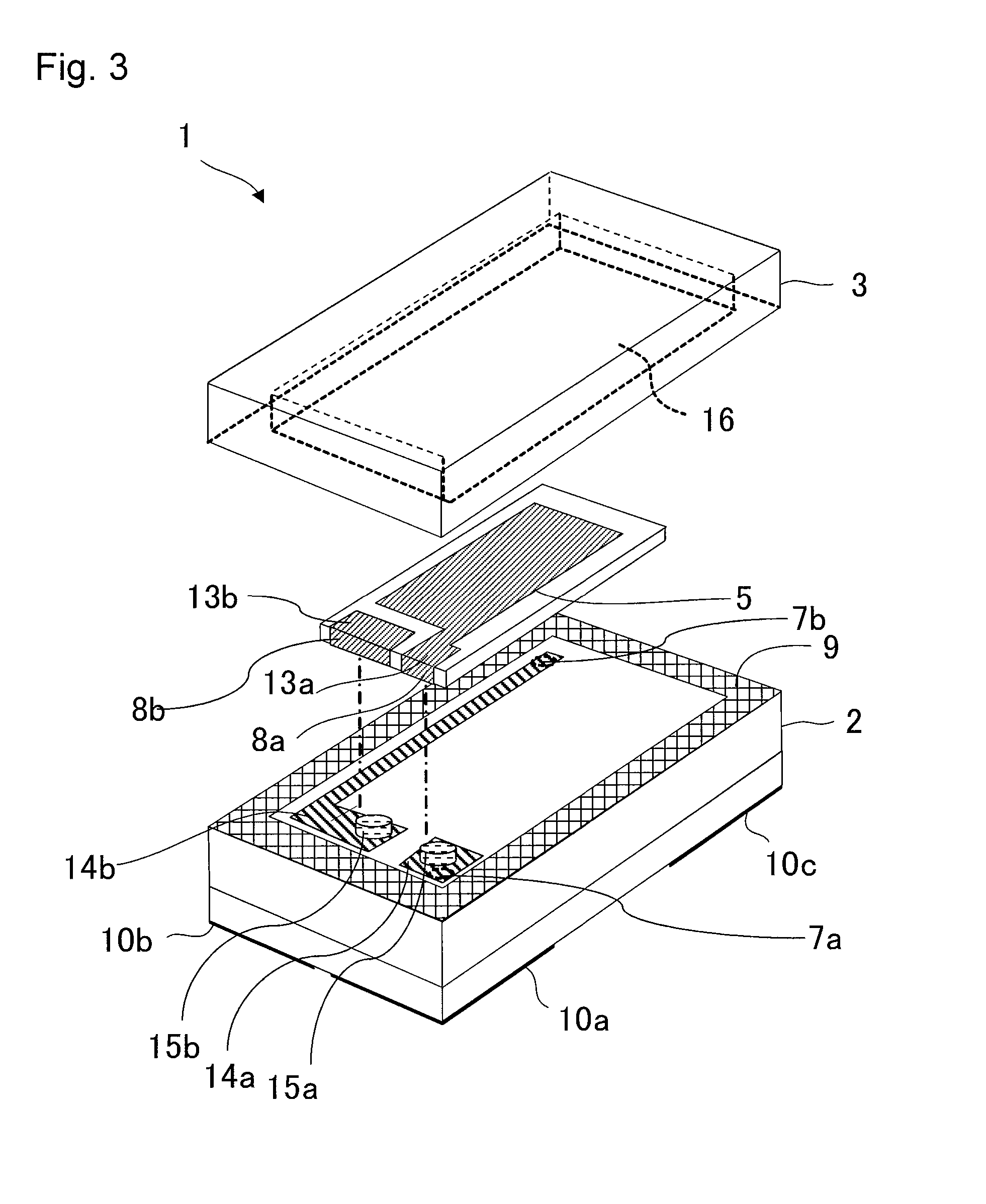
[0028]FIG. 3 is an exploded perspective view. A cover substrate 3 is omitted in FIG. 2.

[0029]The piezoelectric vibration device 1 of the present embodiment is a box-shaped laminate of a base substrate 2 and a cover substrate 3 facing and bonded to the base substrate 2. Further, the piezoelectric vibration device 1 is a surface-mounted piezoelectric vibration device that includes a piezoelectric vibrating reed 4 housed inside a cavity 16 formed between the base substrate 2 and the cover substrate 3. The piezoelectric vibrating reed 4 is held to the base substrate 2 in a cantilever fashion on one of the shorter sides of the piezoelectric vibrating reed 4.

[0030]As illustrate...

second embodiment

[0050]FIG. 4 is a cross sectional view of a piezoelectric vibration device 1 according to Second Embodiment of the present invention taken along the longer side through a routing electrode 14a, as viewed from the side of a piezoelectric vibrating reed 4. Second Embodiment differs from First Embodiment in that the base substrate 2 is provided as a depressed substrate, and the cover substrate 3 as a plate-like substrate. The other configuration is substantially the same as that described in First Embodiment. In the following, descriptions will be made with primary focus on these differences, using the same reference numerals for the same members and for members having the same functions.

[0051]The cover substrate 3 is a plate-like substrate configured from an insulator, a semiconductor, or a metal. The base substrate 2 has a rectangular depression in which the piezoelectric vibrating reed 4 is contained. Upon mating the substrates 2 and 3, the depression becomes the cavity 16 that hous...

third embodiment

[0053]FIG. 5 is a schematic view showing a top surface of a piezoelectric vibration device 1 according to Third Embodiment of the present invention. The cover substrate 3 is omitted in FIG. 5. Third Embodiment differs from First Embodiment in that the piezoelectric vibrating reed 4 is held with bumps at three locations. The other configuration is substantially the same as that described in First Embodiment. In the following, descriptions will be made with primary focus on these differences, using the same reference numerals for the same members and for members having the same functions.

[0054]In the present embodiment, as illustrated in FIG. 5, the piezoelectric vibrating reed 4 is bonded to the base substrate 2 with three bumps. Specifically, a first metal bump 20b and a second metal bump 20a are disposed in the configuration described in First Embodiment. Additionally, in the present embodiment, the mount electrode 13b electrically connected to the first metal bump 20b is also conn...


PUM


Abstract

A piezoelectric vibration device is provided that can reduce the stress and strain that transmit through a base substrate. The piezoelectric vibration device includes a piezoelectric vibrating reed that oscillates in an AT mode, and that includes excitation electrodes respectively formed on the front and back surfaces of the reed. One of the excitation electrodes is connected to the base substrate via a metal bump on a center line passing across the shorter sides of the piezoelectric vibrating reed and in the vicinity of one of the shorter sides of the piezoelectric vibrating reed. The other excitation electrode is connected to the base substrate via a metal bump on the same side as the above shorter side, and in the vicinity of a portion where the shorter side of the piezoelectric vibrating reed crosses one of the longer sides of the piezoelectric vibrating reed.

Description

RELATED APPLICATIONS[0001]This application claims priority under 35 U.S.C. §119 to Japanese Patent Application No. 2011-190575 filed on Sep. 1, 2011, the entire content of which is hereby incorporated by reference.BACKGROUND OF THE INVENTION[0002]1. Field of the Invention[0003]The present invention relates to piezoelectric vibration devices mounting electronic elements.[0004]2. Description of the Related Art[0005]Electronic devices using a surface-mounted small package have been commonly used for portable information terminals such as cell phones that have become pervasive over the last years. For example, devices such as a vibrator, an MEMS, a gyrosensor, and an acceleration sensor are structured to include an electronic element housed inside a package of a hollow cavity structure. In one known type of a package having a hollow cavity structure, for example, a base substrate and a cover substrate are bonded to each other for air-tight sealing. With the recent trend for miniaturizat...

Claims


Application Information

Patent Timeline
Patent Type & Authority Applications(United States)
IPC IPC(8): H01L41/053H03B5/32
CPCH03H9/1021H03H9/0519H02N2/04H10N30/80
Inventor YOSHIDA, YOSHIFUMI
Owner SII CRYSTAL TECH
Why Eureka
Try Eureka