Signal Demodulation Method

a signal demodulation and signal technology, applied in the field of signal processing, can solve the problems of poor demodulation performance of cck transmission using this method, large consumption of resources and processing time, etc., and achieve the effect of reducing the effect of noise on signal and improving signal demodulation performan

Active Publication Date: 2013-03-07
OMNIVISION TECH (SHANGHAI) CO LTD
View PDF5 Cites 2 Cited by
  • Summary
  • Abstract
  • Description
  • Claims
  • Application Information

AI Technical Summary

Benefits of technology

[0024]By using the above technical solution, the present invention is capable of sufficiently reducing the effect of noise on signal and effectively improving the signal demodulation performance.

Problems solved by technology

The correlation matching usually employs FWT (Fast Wavelet Transform) algorithm to reduce calculation amount, but still consumes great resource and processing time.
Although the majority logic decoding method has advantages of simple algorithm, less resource requirement and high processing speed, CCK transmission employing this method has poor demodulation performance.

Method used


Image

  • Signal Demodulation Method
  • Signal Demodulation Method
  • Signal Demodulation Method

Examples


case 1

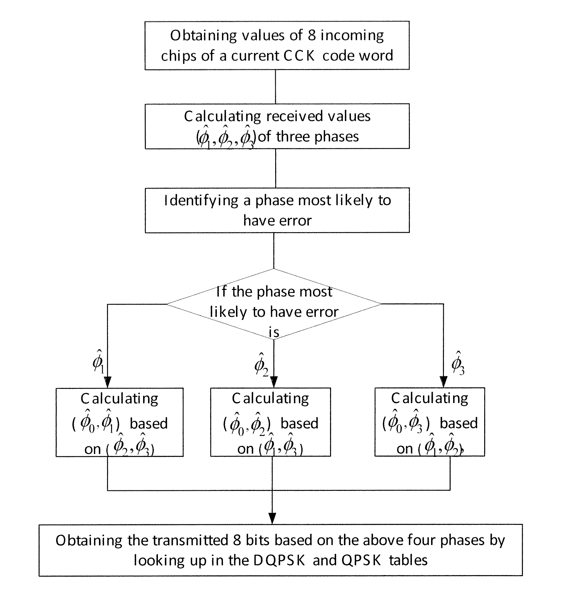
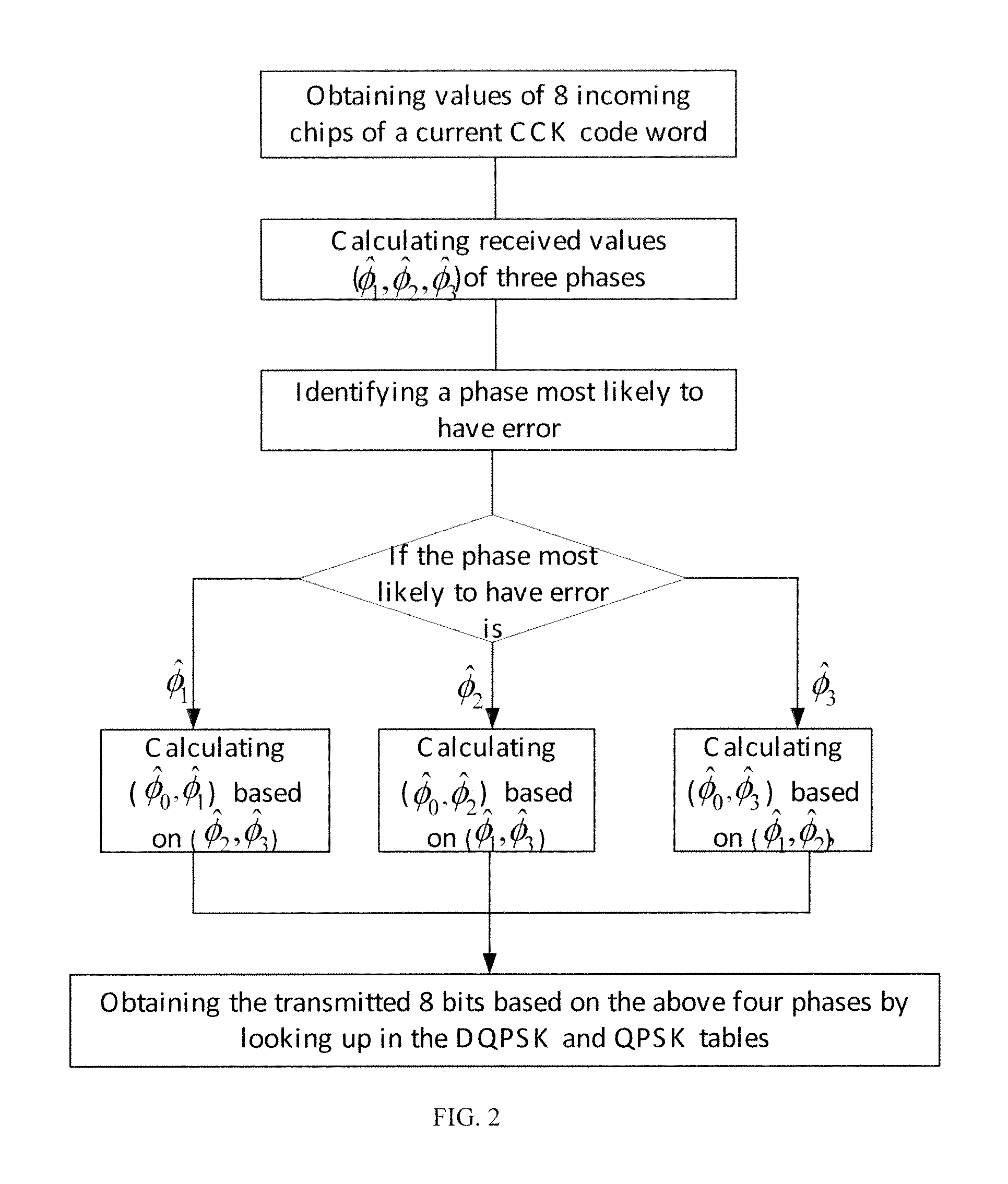
[0044] if the most unreliable phase is φ1, then φ1 and φ0 can be determined by equation (4):

exp(j*)=r1*exp(−j*({circumflex over (φ)}2+{circumflex over (φ)}3))−r3*exp(−j*{circumflex over (φ)}3)+r5*exp(−j*{circumflex over (φ)}2)+r7

exp(j*)=r0*exp(−j*({circumflex over (φ)}2+{circumflex over (φ)}3))+r2*exp(−j*{circumflex over (φ)}3)+r4*exp(−j*{circumflex over (φ)}2)−r6

exp(j*)=exp(j*)*exp(−j*{circumflex over (φ)}0)  (4)

case 2

[0045] if the most unreliable phase is {circumflex over (φ)}2, then {circumflex over (φ)}2 and {circumflex over (φ)}0 can be determined by equation (5):

exp(j*)=r2*exp(−j*({circumflex over (φ)}1+{circumflex over (φ)}3))−r3*exp(−j*{circumflex over (φ)}3)+r6*exp(−j*{circumflex over (φ)}1)+r7

exp(j*)=r0*exp(−j*(φ1+φ3))+r1*exp(−j*φ3)+r4*exp(−j*φ1)−r5

exp(j*)=exp(j*)*exp(−j*φ0)  (5)

case 3

[0046] if the most unreliable phase is {circumflex over (φ)}3, then {circumflex over (φ)}3 and {circumflex over (φ)}0 can be determined by equation (6):

exp(j*)=r4*exp(−j*({circumflex over (φ)}1+{circumflex over (φ)}2))+r5*exp(−j*{circumflex over (φ)}2)−r6*exp(−j*{circumflex over (φ)}1)+r7

exp(j*)=r0*exp(−j*({circumflex over (φ)}1+{circumflex over (φ)}2))+r1*exp(−j*{circumflex over (φ)}2)+r2*exp(−j*{circumflex over (φ)}1)−r3

exp(j*)=exp(j*)*exp(−j*{circumflex over (φ)}0)  (6)

[0047]Step 5: look up in tables (Table 1 and Table 2) to obtain incoming bits based on the determination values of the four phases.

[0048]In particular, in this embodiment, corresponding 8 bits can be obtained by looking up in Table 1 (DQPSK Coding) and Table 2 (QPSK Coding) based on the obtained determination values {circumflex over (φ)}i (i=0, 1, 2, 3).

TABLE 1DQPSK Coding(d0, d1)(0, 0)(0, 1) (1, 1)(1, 0)Even Symbol φ00π / 2π3π / 2Odd Symbol φ0 π3π / 20π / 2

TABLE 2QPSK Coding(d2j, d2j +1)(0, 0)(0, 1)(1, 1)(1, 0)φj0π / 23π / ...


PUM


Abstract

A signal demodulation method is disclosed, which includes: obtaining a complete transmission code word; calculating estimated values of three non-differential phases of the transmission code based on a majority logic; identifying a most unreliable phase among three non-differential phases and determining the other two reliable phases to obtain their determination values; calculating determination values of the rest two phases based on the two determined phases; and looking up in tables based on determination values of the four phases to obtain incoming bits. The demodulation method of the present invention is capable of sufficiently reducing the effect of noise on signal and effectively improving the signal demodulation performance.

Description

CROSS-REFERENCE TO RELATED APPLICATIONS[0001]This application claims the priority of Chinese patent application number 201110264491.7, filed on Sep. 7, 2011, the entire contents of which are incorporated herein by reference.TECHNICAL FIELD[0002]The present invention relates to the field of signal processing, and more particular, to a signal demodulation method.BACKGROUND[0003]IEEE 802.11b protocol has adopted CCK (Complementary Code Keying) modulation for 11 Mbps data rates. CCK is defined by a set of 256 code words, and each of the code words consists of 8 complex chips. Such code word set is quasi-orthogonal. If common phases between code words are not taken into consideration, the set of 256 code words is actually a set of 64 code words referred to as basic CCK code word set.[0004]In CCK modulation, an incoming bit stream is divided into groups of 8 bits, denoted by (d0, d1, d2, d3, d4, d5, d6, d7). In each group of the 8 incoming bits, the first two bits (d0, d1) are encoded usi...

Claims


Application Information

Patent Timeline
Patent Type & Authority Applications(United States)
IPC IPC(8): H04L27/06
CPCH04L23/02
Inventor ZHANG, YUN
Owner OMNIVISION TECH (SHANGHAI) CO LTD
Why Eureka
Try Eureka