

Attenuated splitter module for low count output channels and related assemblies and methods
a splitter module and low-count technology, applied in the field of splitter modules and related assemblies, can solve the problems of limited number of adapters on the distribution panel of these cabinets and closures, inability to accommodate the installation of large cabinets, and inability to meet the needs of multi-dwelling units and high-rise building applications with architectural space restrictions
- Summary
- Abstract
- Description
- Claims
- Application Information
AI Technical Summary
Benefits of technology
Problems solved by technology
Method used
Image

Examples
Embodiment Construction
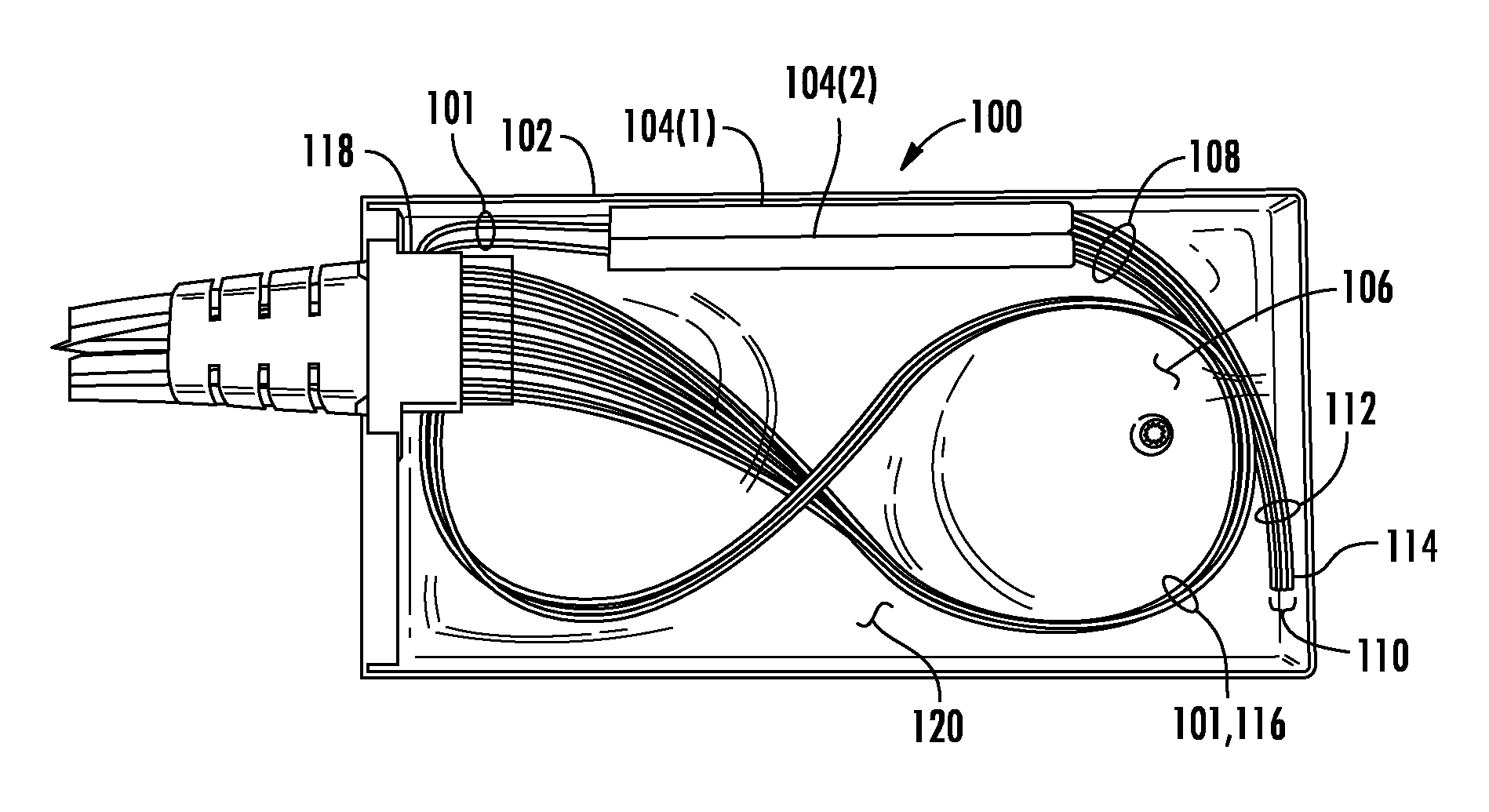
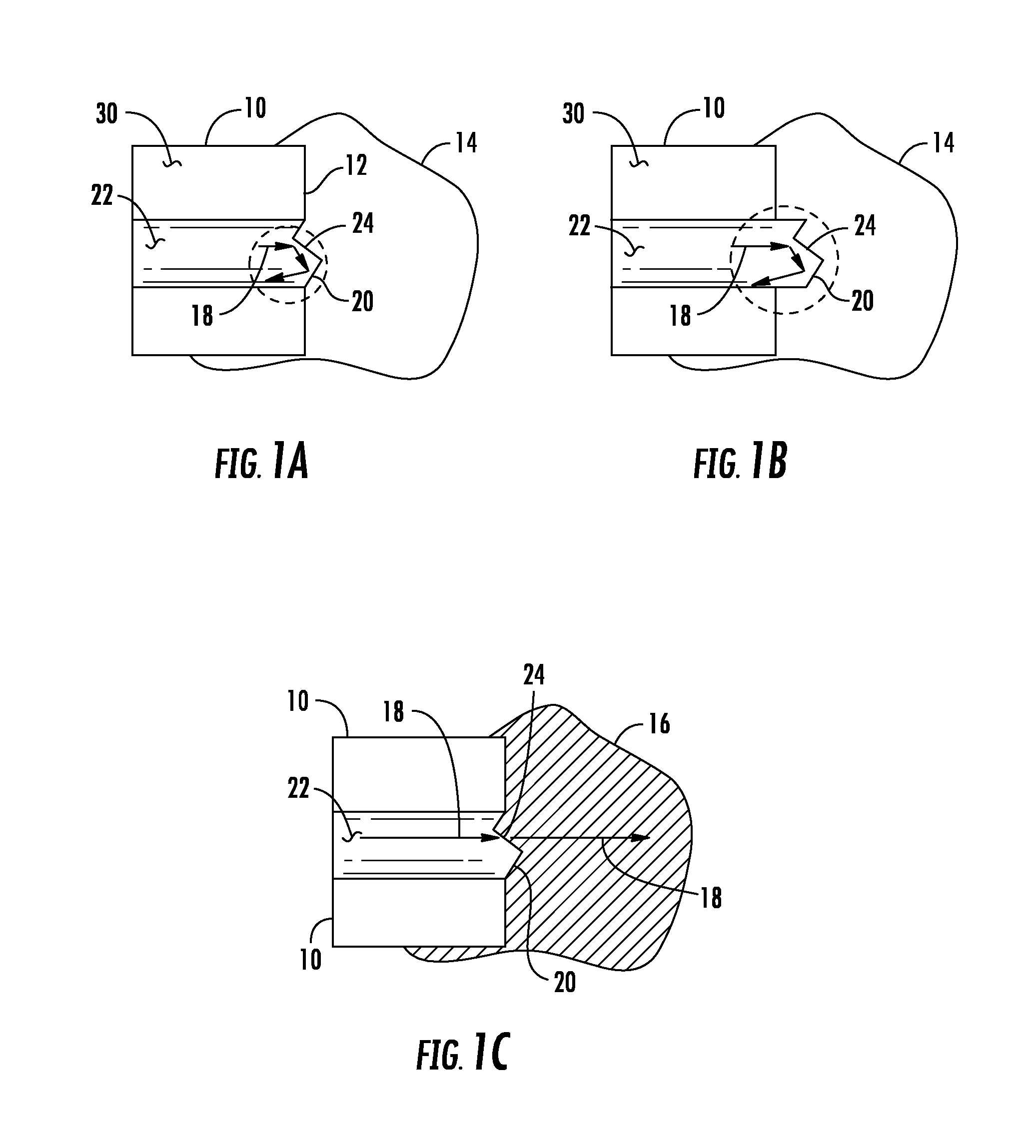
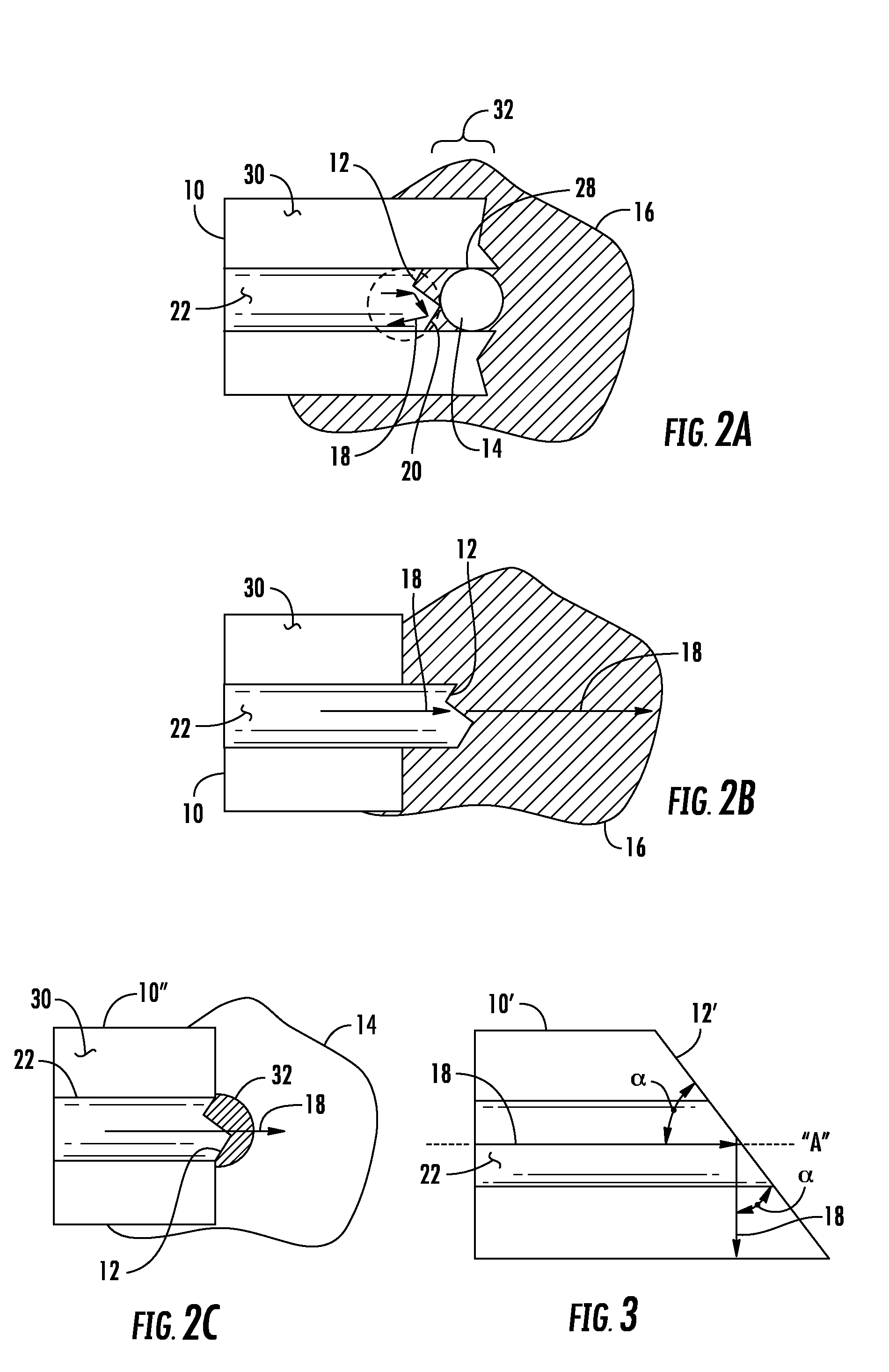
[0008]Embodiments disclosed herein include a splitter module, comprising an enclosure and a splitter with one or more splitter legs mounted in the enclosure. Each splitter leg has a first optical fiber therein and extends for a certain length from the splitter. The length may be up to at least about 70 mm or longer. At least one of the splitter legs, and, thereby, the first optical fiber, is cut. The cut may be at an angle to the longitudinal axis of the first optical fiber. The angle may be about 45 degrees. The coating may be stripped off such that the cut end of the glass fiber of the first optical fiber is exposed a certain distance. The distance may be up to at least about 5 mm or longer. The cut end of the glass fiber of the first optical fiber positions in the interior of the enclosure. A glass-index-matching material, as non-limiting examples, silicone, epoxy and polyurethane, at least partially fills the interior of the enclosure such that the cut end of the first optical f...
PUM
 Abstract
Description
Claims
Application Information