
Network virtualization

a network virtualization and network technology, applied in the field of network virtualization, can solve the problems of insufficient scaling out of network forwarding fabric in this fashion, difficult robust version of network scaling out, and more subtle challenges of networks

Active Publication Date: 2013-03-07
NICIRA
View PDF14 Cites 179 Cited by
  • Summary
  • Abstract
  • Description
  • Claims
  • Application Information

AI Technical Summary

Benefits of technology

The invention describes a system that allows multiple users to have separate logical data paths through the same network infrastructure. The system uses software tools to virtualize control of the shared switch elements and network, so that each user only has access to their own data path. This prevents users from seeing or controlling each other's data paths while sharing the same switching elements. The technical effect is a more secure and efficient network for multiple users.

Problems solved by technology

While computation and storage are scale-out success stories, networks pose a more subtle challenge to the scale-out paradigm.
However, scaling out the network forwarding fabric in this fashion is not sufficient.
A robust version of network scale-out is difficult because—unlike computation, storage, and simple packet delivery—there is no well-accepted abstraction for this more general form of global network behavior; instead, global network behavior is typically defined only in terms of the set of individual router / switch configurations.
This inability to add new networking hardware without manual configuration is a barrier to the fully faithful scaling-out of network functionality.
However, this approach limits to running single logical forwarding element per physical switch.
However, this approach is often used to introduce new functionality when the operator cannot or does not want to change (for administrative or implementation reasons) the features in the underlying hardware.

Method used


Image

  • Network virtualization
  • Network virtualization
  • Network virtualization

Examples


Embodiment Construction

[0051]In the following detailed description of the invention, numerous details, examples, and embodiments of the invention are set forth and described. However, it will be clear and apparent to one skilled in the art that the invention is not limited to the embodiments set forth and that the invention may be practiced without some of the specific details and examples discussed.

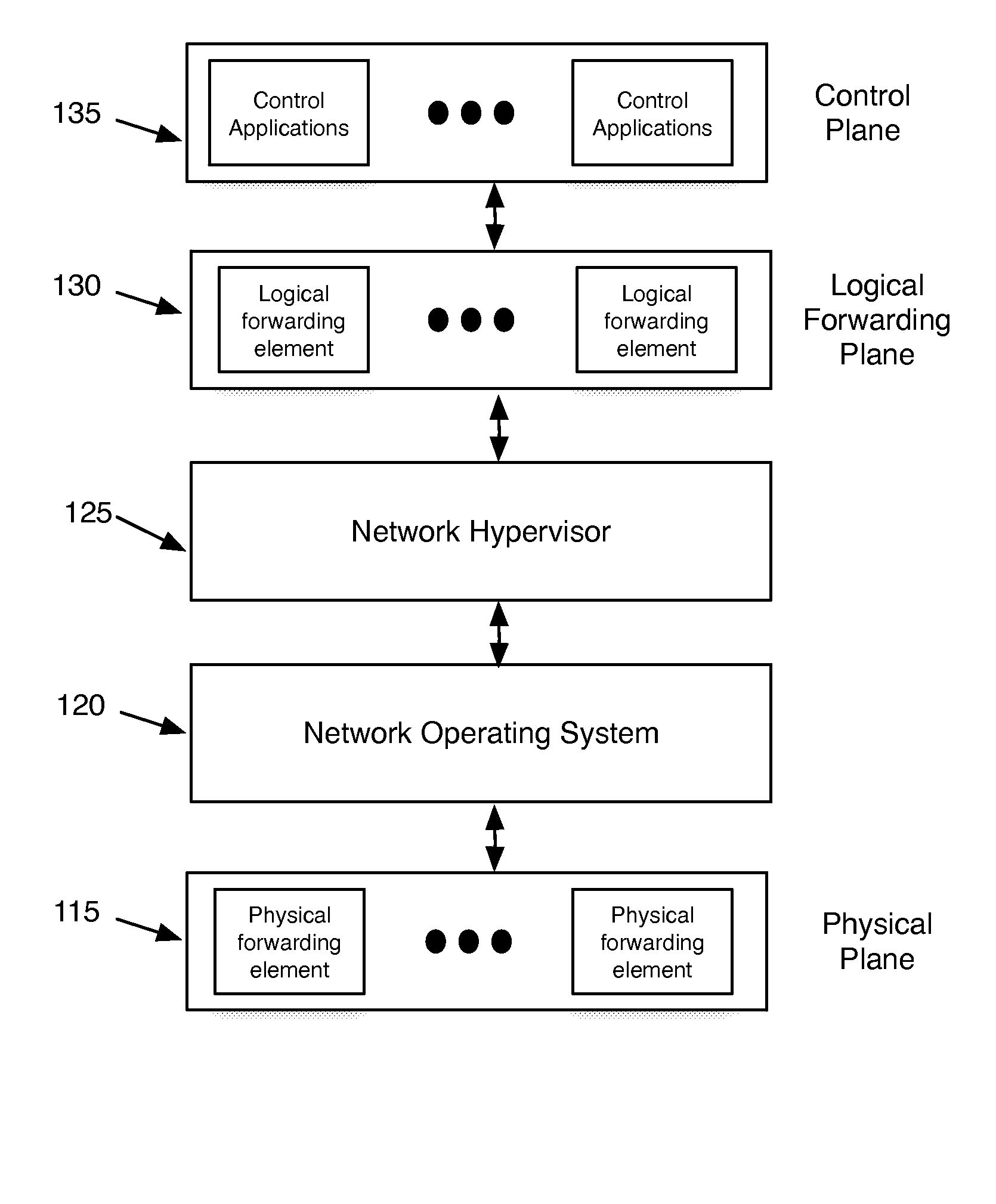
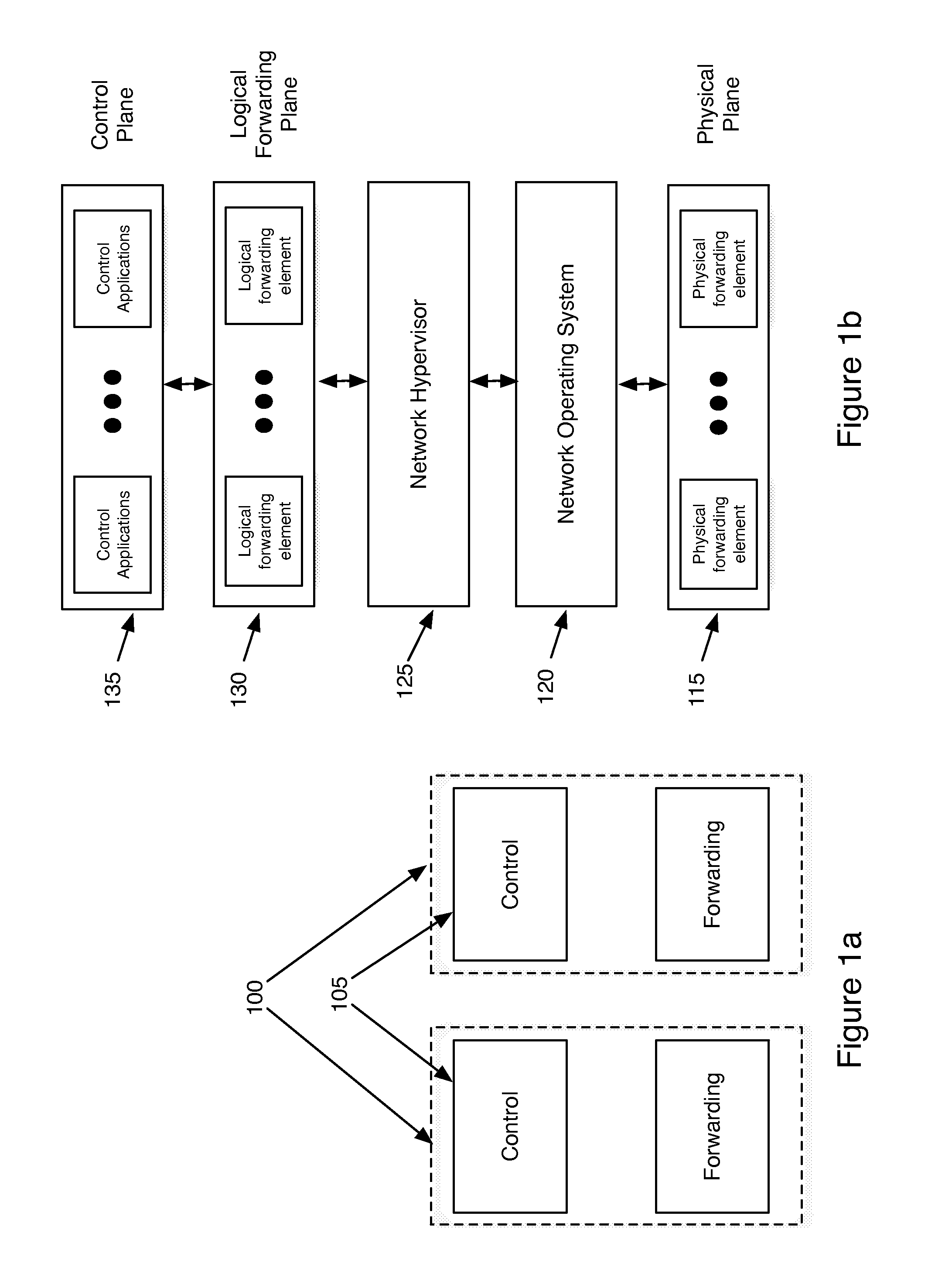
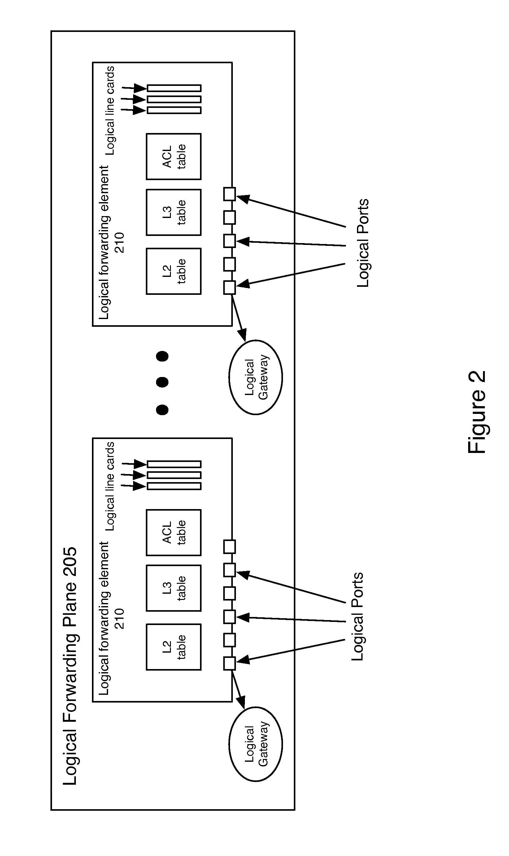
[0052]Some embodiments of the invention provide a robust scaling-out of network functionality by providing a software layer, called the network hypervisor, that sits between the network forwarding functions (i.e., the forwarding plane) and the network control interfaces (i.e., the control plane). The network hypervisor of some embodiments provides a logical abstraction of the network's forwarding functionality, so that network operators make their control decisions in terms of this abstraction, independent of the details of the underlying networking hardware. The network hypervisor of some embodiments may then...


PUM


Abstract

Some embodiments of the invention provide a robust scaling-out of network functionality by providing a software layer, called the network hypervisor, that sits between the network forwarding functions (i.e., the forwarding plane) and the network control interfaces (i.e., the control plane). The network hypervisor of some embodiments provides a logical abstraction of the network's forwarding functionality, so that network operators make their control decisions in terms of this abstraction, independent of the details of the underlying networking hardware. The network hypervisor of some embodiments may then “compile” commands placed against this abstraction into configurations of the underlying hardware. Accordingly, in some embodiments, there are two design challenges: (1) the choice of the network abstraction, and (2) the technology needed to compile the logical “abstract” controls into low-level configurations.

Description

CLAIM OF BENEFIT TO PRIOR APPLICATION[0001]This application claims benefit to U.S. Provisional Patent Application 61 / 361,912, filed on Jul. 6, 2010; U.S. Provisional Patent Application 61 / 361,913, filed on Jul. 6, 2010; U.S. Provisional Patent Application 61 / 429,753, filed on Jan. 4, 2011; U.S. Provisional Patent Application 61 / 429,754, filed on Jan. 4, 2011; U.S. Provisional Patent Application 61 / 466,453, filed on Mar. 22, 2011; U.S. Provisional Patent Application 61 / 482,205, filed on May 3, 2011; U.S. Provisional Patent Application 61 / 482,615, filed on May 4, 2011; U.S. Provisional Patent Application 61 / 482,616, filed on May 4, 2011; U.S. Provisional Patent Application 61 / 501,743, filed on Jun. 27, 2011; and U.S. Provisional Patent Application 61 / 501,785, filed on Jun. 28, 2011. These provisional applications are incorporated herein by reference.BACKGROUND[0002]The mantra of modern datacenters is scale out, not up. To handle ever-increasing aggregate capacities, these datacenters ...

Claims


Application Information

Patent Timeline
IPC IPC(8): G06F15/16H04L45/586H04L49/111
CPCH04L41/0896H04L49/70G06F11/07H04L49/1546H04L12/5689H04L12/5696H04L41/0893H04L49/3063G06F15/17312H04L45/586H04L49/00H04L41/0895H04L41/122H04L41/0894H04L45/036H04L45/76H04L12/4633H04L47/783H04L45/00H04L61/5007H04L2101/622H04L45/02H04L41/0816H04L41/0853
Inventor KOPONEN, TEEMUCASADO, MARTININGRAM, PAUL S.LAMBETH, W. ANDREWBALLAND, III, PETER J.AMIDON, KEITH E.WENDLANDT, DANIEL J.
Owner NICIRA
Learn More