Mounting a Base Plate on Upstanding Fasteners of a Support

Inactive Publication Date: 2013-03-14
ROSENDAHL DEAN R
View PDF7 Cites 13 Cited by
  • Summary
  • Abstract
  • Description
  • Claims
  • Application Information

AI Technical Summary

Benefits of technology

[0036]The washer is placed in an infrastructure component mounting hole which is round matching the mounting washer, thereby allowing the washer to rotate within the hole 360 degrees, and allowing the stepped section o

Problems solved by technology

There are at times difficulties in setting bolts or screw fasteners in an exact location in the concrete base to line up and fit with the mounting holes in infrastructure components and to align the component to its desired position.
That is the loca

Method used


Image

  • Mounting a Base Plate on Upstanding Fasteners of a Support
  • Mounting a Base Plate on Upstanding Fasteners of a Support
  • Mounting a Base Plate on Upstanding Fasteners of a Support

Examples


Embodiment Construction

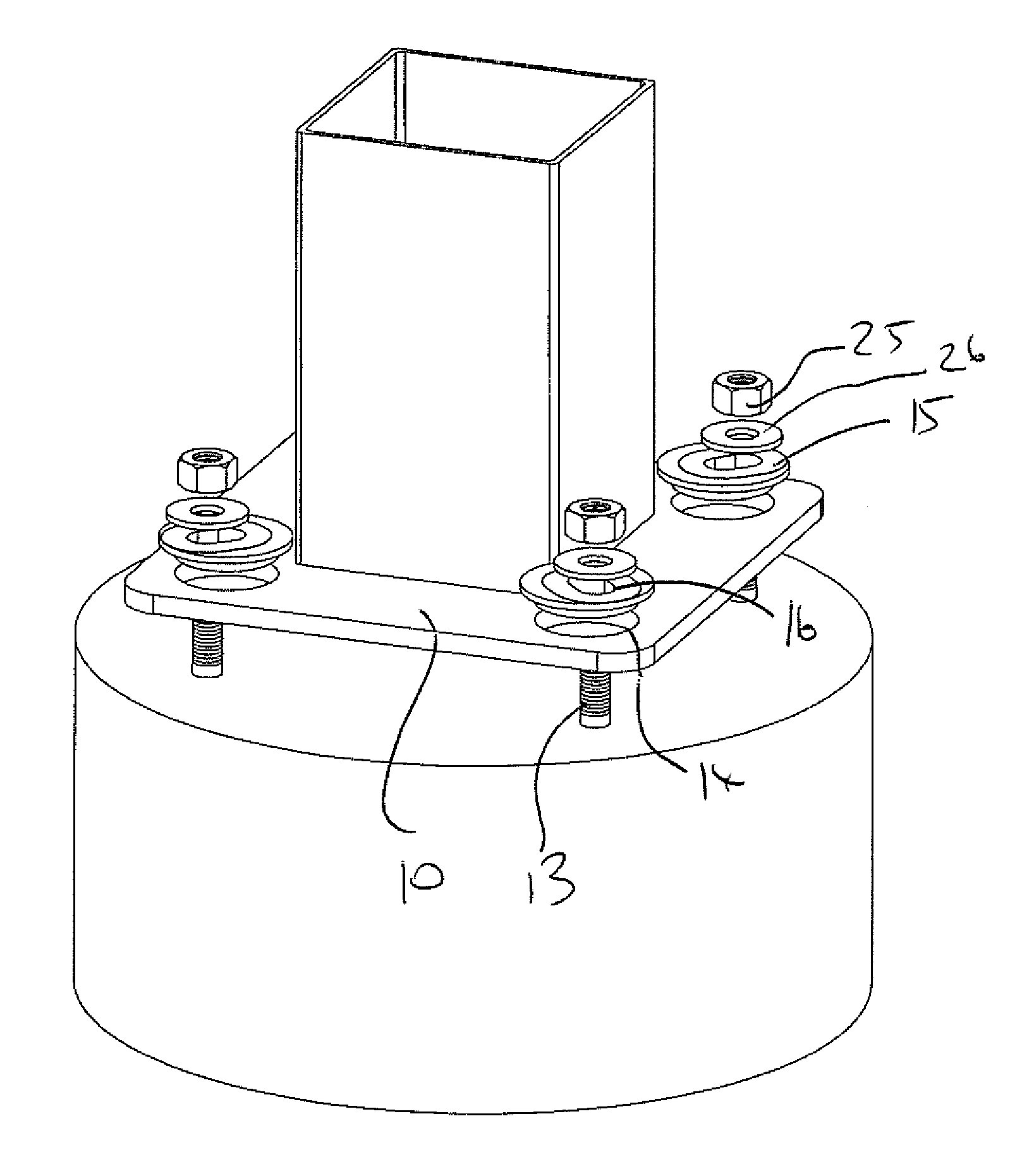
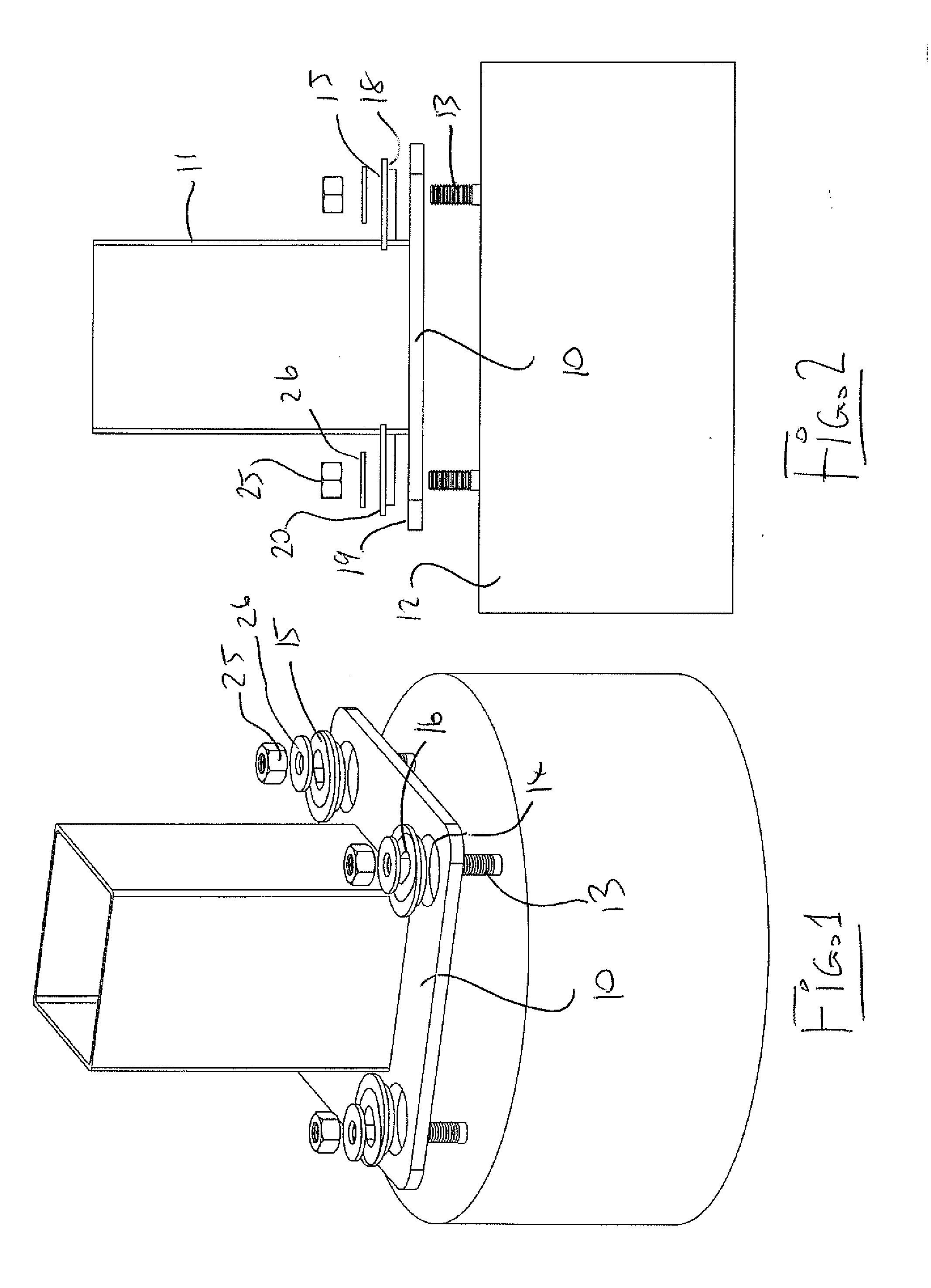
[0049]One embodiment of the method of the present invention is shown in FIGS. 1 and 2. This includes a base plate 10 carrying a post 11. The base plate can be of any suitable shape and may be integral or formed in sections. It is in most cases planar but does not have to be. As shown the post 11 is welded to the base plate 10 but other fastening systems may be used.

[0050]The base plate is attached to a support 12 which is typically formed of a cast concrete with a plurality of upstanding threaded fasteners 13 cast into the support at spaced positions in an array on the support. As the fasteners 13 are cast in place, they are typically inaccurately located due to casting errors, or require very close attention to provide suitable accuracy.

[0051]Thus the plurality of threaded fasteners 14 are located on the support 12 so as to stand upwardly from the support at fixed locations thereon.

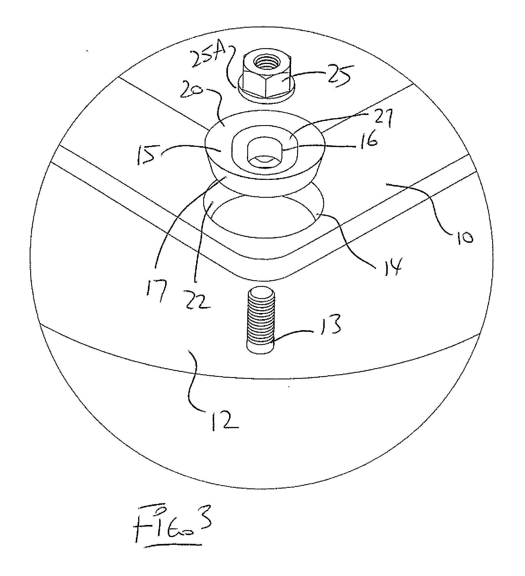
[0052]The base plate 10 has a plurality of circular plate holes 14 therein for engaging over the fast...


PUM

PropertyMeasurementUnit
Fractionaaaaaaaaaa

Abstract

In a method for mounting a base plate on upstanding threaded fasteners of for example a cast concrete support there is provided in the base plate a plurality of adjustable disk members each defining an elongate fastening slot therein for receiving a respective one of the threaded fasteners therein at different positions therealong. Each of the adjustable disk members has a circular outer periphery engaging into a respective plate holes such that the adjustable disk member is supported in the base plate. Each of the adjustable disk members is rotated in its respective plate hole relative to the base plate so as to move the fastening slots relative to the base plate so as to match the fixed located positions of the fasteners.

Description

[0001]This invention relates to a method for mounting a base plate on upstanding fasteners of a support.[0002]The invention is particularly applicable for mounting a base plate onto upstanding screw fasteners which are cast in a concrete support so that the fasteners stand upwardly from the concrete support for engaging through pre-formed holes in the base plate.[0003]There are at times difficulties in setting bolts or screw fasteners in an exact location in the concrete base to line up and fit with the mounting holes in infrastructure components and to align the component to its desired position.[0004]That is the location of the screw fasteners may not directly align with the holes and when engaged through the holes may not locate the base plate or components carried on the base plate at the exact correct location to match with or cooperate with other components.SUMMARY OF THE INVENTION[0005]It is one object of the invention to provide a method for mounting a base plate on upstandi...

Claims


Application Information

Patent Timeline
IPC IPC(8): B23P11/00B23P17/00
CPCE04H5/04E04H12/2261Y10T29/49826F16B5/025Y10T29/49963E04B1/4157
Inventor ROSENDAHL, DEAN R.
Owner ROSENDAHL DEAN R
Why Eureka
Try Eureka