
Display apparatus

a technology for display apparatuses and displays, applied in static indicating devices, cathode-ray tube indicators, instruments, etc., can solve the problems of low luminance generation efficiency, impaired visibility of display apparatuses, and increase of consumption power and costs, so as to improve luminance, correct color shift, and improve visibility.

Active Publication Date: 2013-03-14
SHARP KK
View PDF11 Cites 24 Cited by
  • Summary
  • Abstract
  • Description
  • Claims
  • Application Information

AI Technical Summary

Benefits of technology

The invention is a display apparatus that can correct color shift caused by external light and the backlight section. The apparatus includes a display section with a color filter and a display screen, a backlight section, and a half mirror or external light acquisition section. A spectral characteristic detection section detects the spectral characteristic of the irradiation light and the external light, and a color correction section performs color correction based on the detected characteristics. The control section generates color correction information and supplies it to the color correction section for color correction. This allows for color correction for each area of the screen, preventing deterioration in visibility due to external light or temporal change of the backlight section. The invention also allows for color correction for both outdoor and indoor use, ensuring consistent color reproduction regardless of the placement location.

Problems solved by technology

A display apparatus has a problem of impaired visibility due to higher luminance of external light than luminance of the display apparatus at the time of being used for digital signage, or electronic signage that is placed outdoors, for example.
Further, the luminance of the display apparatus is increased for prevention of an effect of external light, which results in increase of consumption power and costs, thus posing a problem.
That is, in the semi-transmissive liquid crystal display apparatus using a half mirror, the reflective rate of external light is low, which results in low luminance generation efficiency.

Method used


Image

  • Display apparatus
  • Display apparatus
  • Display apparatus

Examples


first embodiment

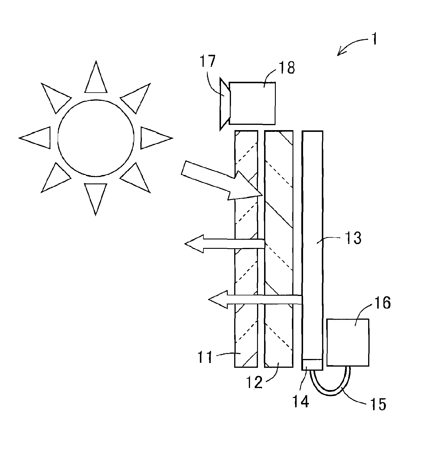
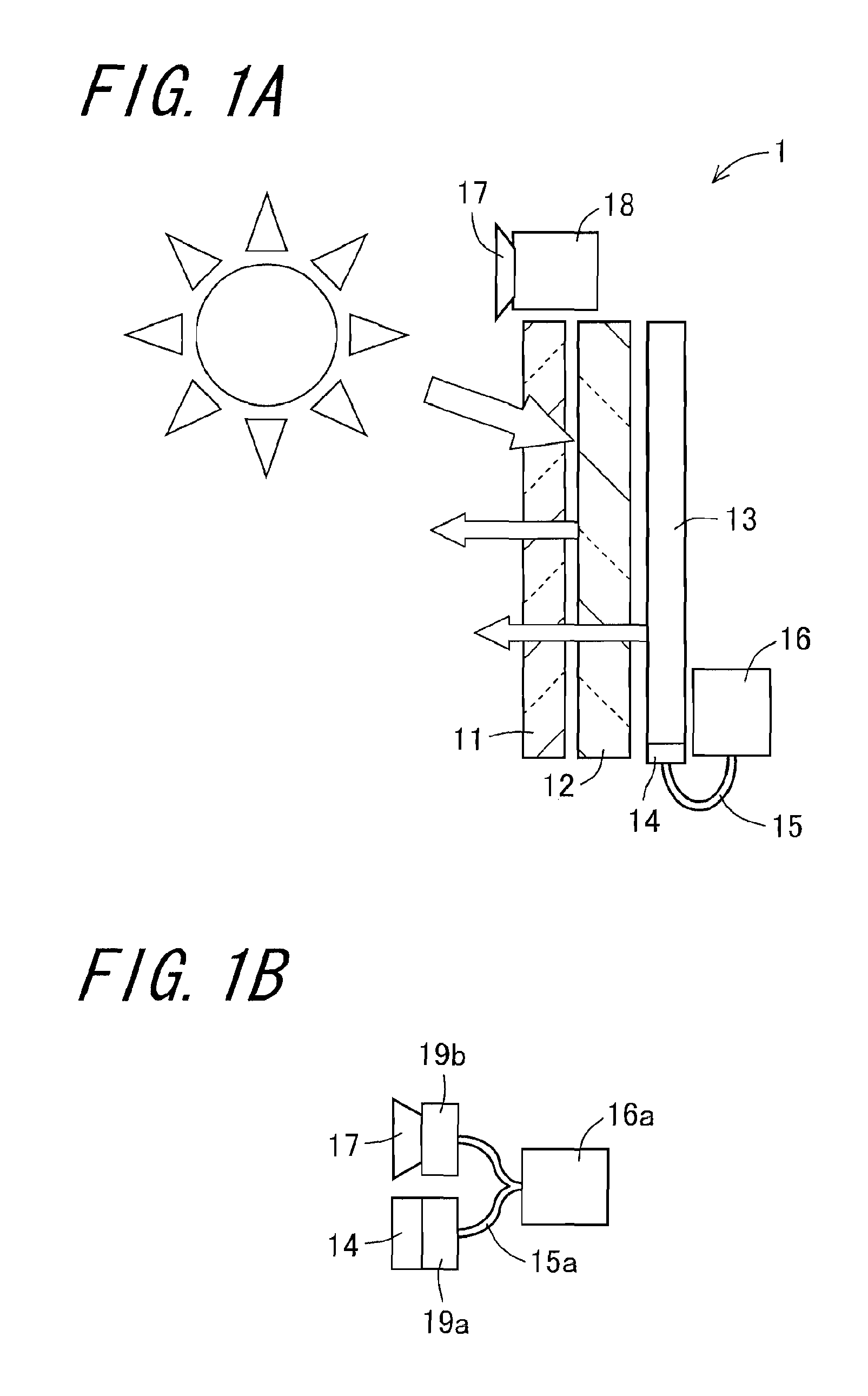
[0106]FIGS. 1A and 1B are side views schematically showing external appearance of a semi-transmissive liquid crystal display apparatus 1 according to the invention. FIG. 1A is an external view of the semi-transmissive liquid crystal display apparatus 1 seen from a lateral side. The semi-transmissive liquid crystal display apparatus 1, which is a display apparatus, comprises a liquid crystal display (abbreviated as LCD) module 11, a half mirror 12, a backlight 13, diffuser plates 14 and 17, an optical fiber 15, a first spectral radiance sensor 16, and a second spectral radiance sensor 18.

[0107]The LCD module 11 as a display section is composed of, for example, a liquid crystal panel and displays image information. The LCD module 11 has a color filter and a display screen, which are not shown, and light is passed through the color filter from a back thereof so as to produce color of image information to be displayed. The half mirror 12 is arranged at a back of the LCD module 11, namel...

second embodiment

[0165]FIG. 12 is a side view schematically showing external appearance of a transmissive liquid crystal display apparatus 2 according to the invention. The transmissive liquid crystal display apparatus 2, which is a display apparatus, comprises an LCD module 21, a backlight 22, a diffuser plate 23, optical fiber 24 and a spectral radiance sensor 25. The LCD module 21, the diffuser plate 23, and the optical fiber 24 and the spectral radiance sensor 25 have the same configuration respectively as the LCD module 11, the diffuser plate 14, the optical fiber 15 and the first spectral radiance sensor 16 as shown in FIG. 1A, and description thereof is omitted for avoiding redundancy.

[0166]The backlight 22 is composed of, for example, an edge light-type backlight, and comprises a light source (not shown) and a light guide plate (not shown). The backlight 22 has at a peripheral section 221 of the backlight 22 an external light intake 222 for taking in external light coming from the front side...

third embodiment

[0182]FIGS. 13A and 13B are side views schematically showing external appearance of a semi-transmissive liquid crystal display apparatus 1A according to the invention. FIGS. 14A and 14B are front views schematically showing external appearance of the semi-transmissive liquid crystal display apparatuses 1A and 1B. FIG. 13A shows external appearance of the semi-transmissive liquid crystal display apparatus 1A seen from a lateral side. In the embodiment, corresponding parts of the configuration in the above-described embodiment are denoted by the same reference numerals, and description thereof is omitted. The semi-transmissive liquid crystal display apparatus 1A, which is a display apparatus, comprises the liquid crystal display (abbreviated as LCD) module 11, the half mirror 12, the backlight 13, the diffuser plates 14 and 17, the optical fiber 15, the first spectral radiance sensor 16, and the second spectral radiance sensor 18.

[0183]The diffuser plate 17 diffuses and transmits the ...


PUM


Abstract

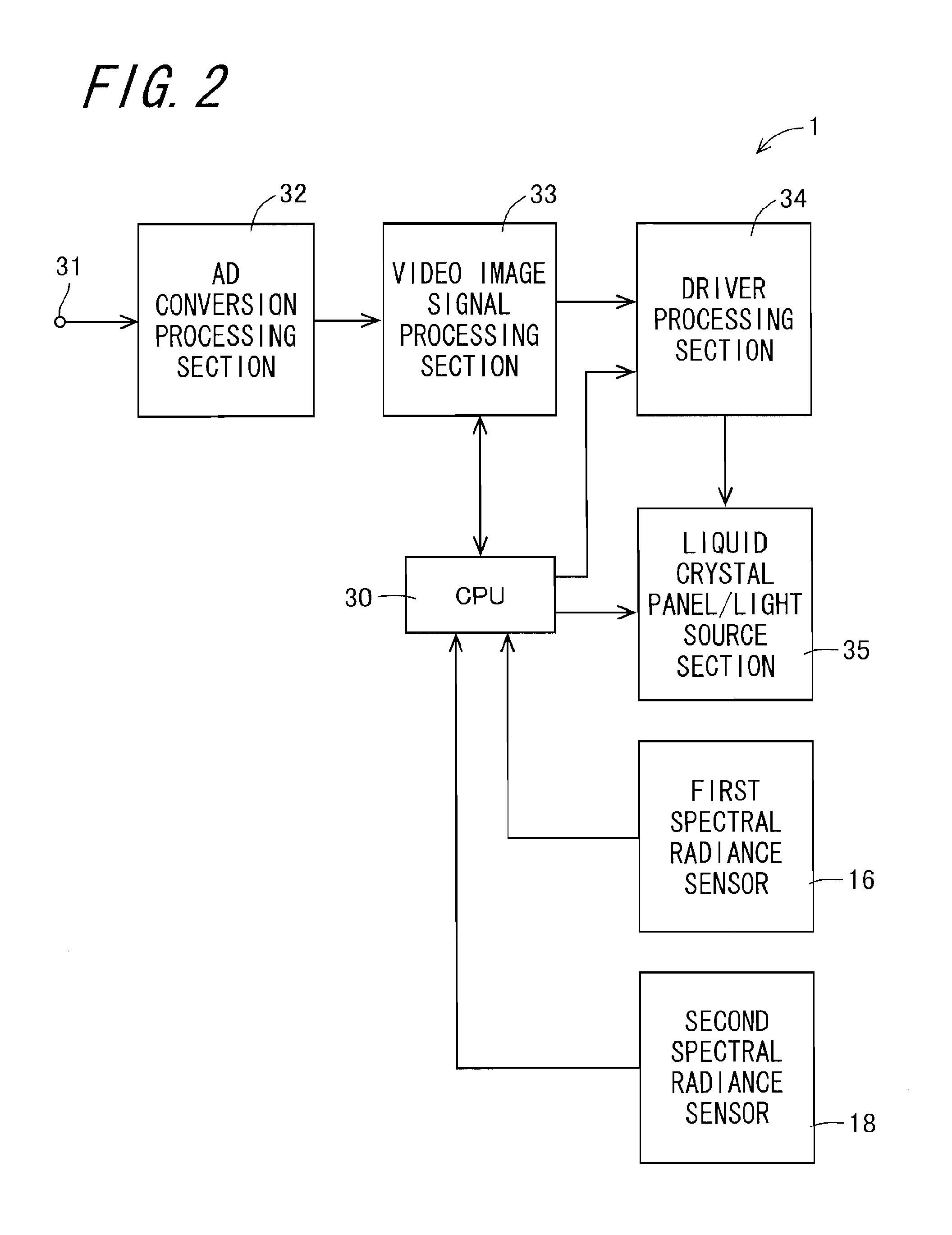
A high luminance display apparatus is provided. When a spectral radiance of a backlight at a time point of factory shipment is less than a spectral radiance of external light, a CPU generates a correction matrix for performing color correction so that color produced by external light, i.e., color produced by reflection light of external light by a half mirror conforms to color produced by only irradiation light of the backlight, transmits the generated correction matrix to a video image signal processing section as parameter information, and causes execution of color correction based on the parameter information. The CPU generates a correction matrix based on a spectral radiance of external light detected by a second spectral radiance sensor, a spectral radiance of the backlight detected at the time point of factory shipment, and spectral transmittance of a color filter as well as a color-matching function.

Description

TECHNICAL FIELD[0001]The present invention relates to a display apparatus capable of performing color correction according to external light.BACKGROUND ART[0002]A display apparatus has a problem of impaired visibility due to higher luminance of external light than luminance of the display apparatus at the time of being used for digital signage, or electronic signage that is placed outdoors, for example. Further, the luminance of the display apparatus is increased for prevention of an effect of external light, which results in increase of consumption power and costs, thus posing a problem. In order to solve these problems, a semi-transmissive liquid crystal display apparatus has been proposed.[0003]The semi-transmissive liquid crystal display apparatus is a liquid crystal display apparatus which is a hybrid type of a transmissive liquid crystal display apparatus of a backlight-type or the like and a reflective liquid crystal display apparatus. The semi-transmissive liquid crystal dis...

Claims


Application Information

Patent Timeline
IPC IPC(8): G09G5/02
CPCG09G3/3406G09G3/3611G09G2300/0456G09G2360/145G09G2320/0666G09G2360/144G09G2320/0626
Inventor SUGIYAMA, KOICHIAKASHI, TAIKOH
Owner SHARP KK
Learn More