

Drawing apparatus, and method of manufacturing article
- Summary
- Abstract
- Description
- Claims
- Application Information
AI Technical Summary
Benefits of technology
Problems solved by technology
Method used
Image

Examples
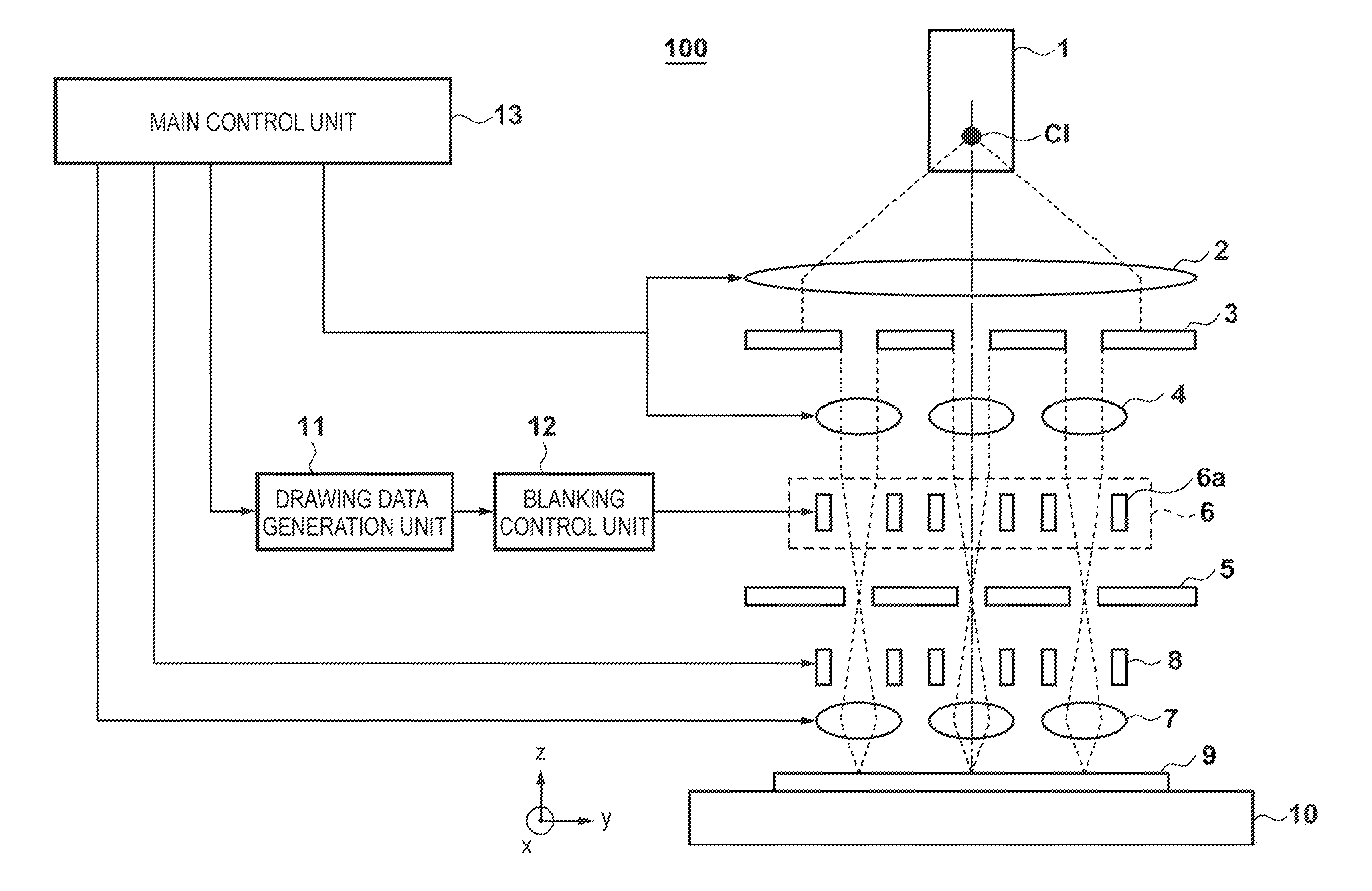
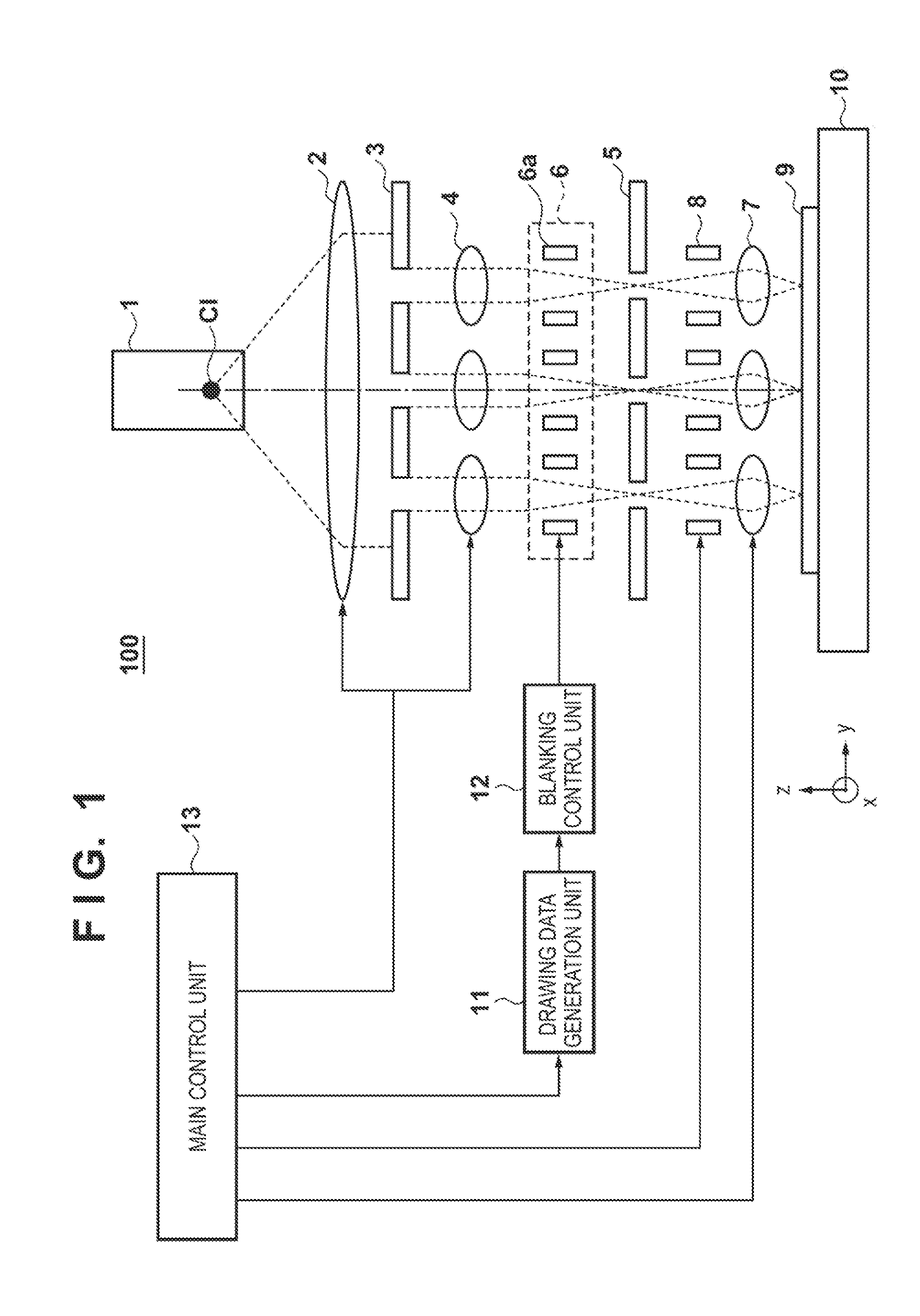
first embodiment
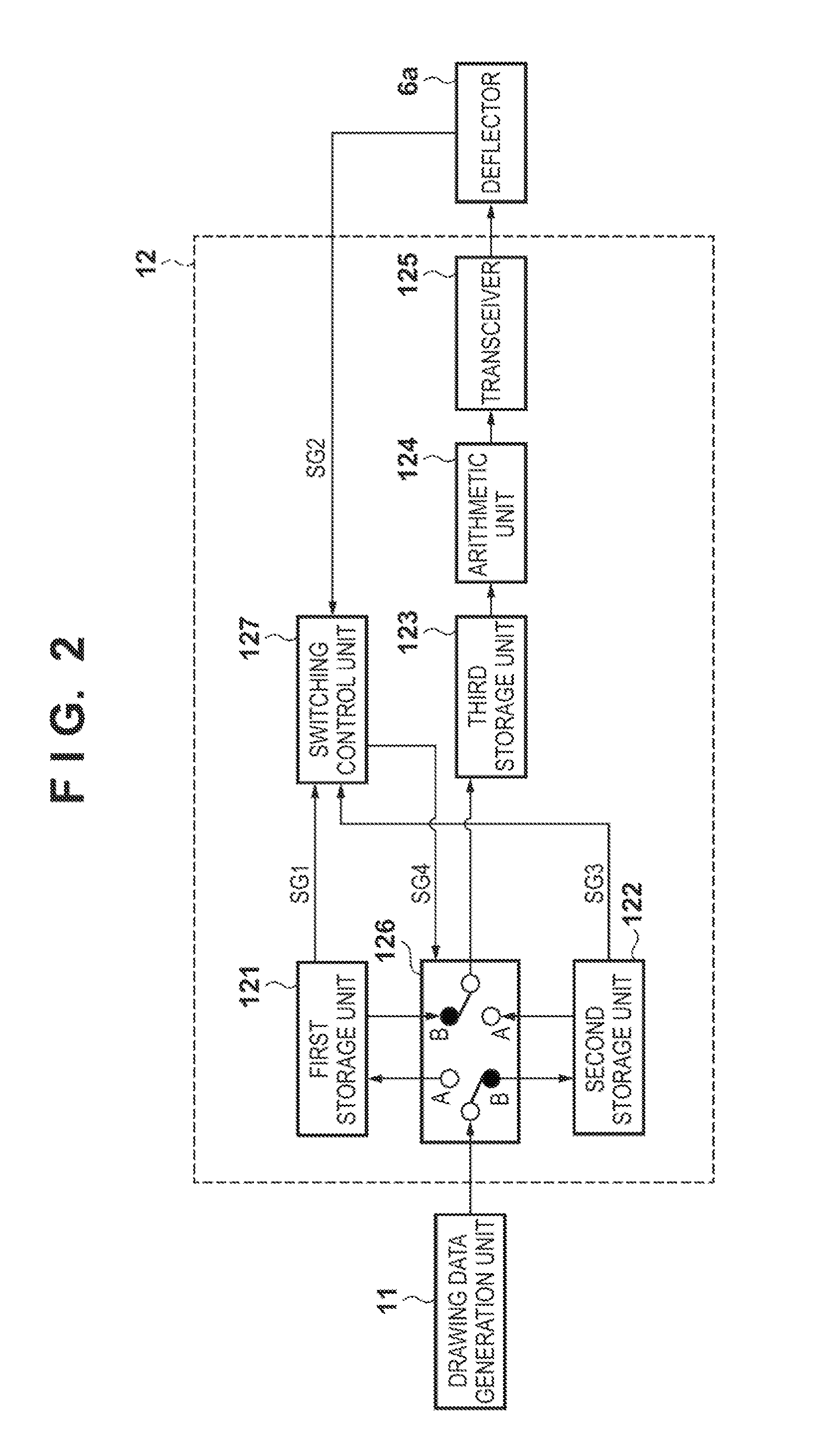
[0034]FIG. 2 is a block diagram showing the configuration of a blanking control unit 12 in the first embodiment. In this embodiment, the blanking control unit 12 includes a first storage unit 121, second storage unit 122, and third storage unit 123 which respectively store drawing data, and the first storage unit 121 and second storage unit 121 are arranged in parallel in the preceding stage of the third storage unit 123,
[0035]The third storage unit 123 has a storage capacity lower than those of the first storage unit 121 and second storage unit 122, and has a storage speed higher than those of the first storage unit 121 and second storage unit 122. More specifically, each of the first storage unit 121 and second storage unit 122 is implemented by a low speed, high capacity storage device, that is,- a nonvolatile storage device such as a hard disk drive (HDD) or a solid-state drive (SSD). Such a storage device has a low storage speed (write speed), but holds data (drawing data) even...
second embodiment
[0049]FIG. 6 is a block diagram showing the configuration of a blanking control unit 12 in the second embodiment. The blanking control unit 12 in the second embodiment is different from the blanking control unit 12 in the first embodiment in that in the former a signal SGS indicating completion of storage of drawing data read out from a first storage unit 121 or a second storage unit 122 in a third storage unit 123 is input to a switching control unit 127.
[0050]The operation sequence of the blanking control unit 12 in the second embodiment will be described with reference to FIGS. 7A and 7B, based on a comparison with the first embodiment. FIG. 7A shows the operation sequence in the first embodiment, and FIG. 7E shows the operation sequence in the second embodiment. In the second embodiment, a standby time ΔTt until completion of an operation of storing drawing data transmitted from a drawing data generation unit 11 in the first storage unit 121 or second storage unit 122 (this oper...
third embodiments
[0056]FIG. 5 is a block diagram showing the configuration of a blanking control unit 12 in the third embodiment. The blanking control unit 12 in the third embodiment is different from the blanking control, unit 12 in the first embodiment in that in the former a signal SG2 indicating completion of driving of a deflector 6a based on drawing data stored in a third storage unit 123 is not input to a switching control unit 127.
[0057]The operation sequence of the blanking control unit 12 in the third embodiment will be described with reference to FIG. 9. In this embodiment, after an operation of storing drawing data B transmitted from a drawing data generation unit 11 in a second storage unit 122 is completed, switching from switch B to switch A in a switching unit 126 is done without waiting until an operation of drawing a pattern corresponding to drawing data A is completed. Therefore, an operation of drawing a pattern corresponding to drawing data A, and an operation of storing drawing...
PUM
 Abstract
Description
Claims
Application Information