
Method for reducing row and column noise in imaging systems

a technology of imaging system and noise reduction, applied in the field of imaging system noise reduction, can solve the problems of headaches for users, uncool array use, and detection array based imaging system, and achieve the effect of reducing the noise in an imag

Active Publication Date: 2013-03-14
BAE SYST INFORMATION & ELECTRONICS SYST INTERGRATION INC
View PDF6 Cites 16 Cited by
  • Summary
  • Abstract
  • Description
  • Claims
  • Application Information

AI Technical Summary

Benefits of technology

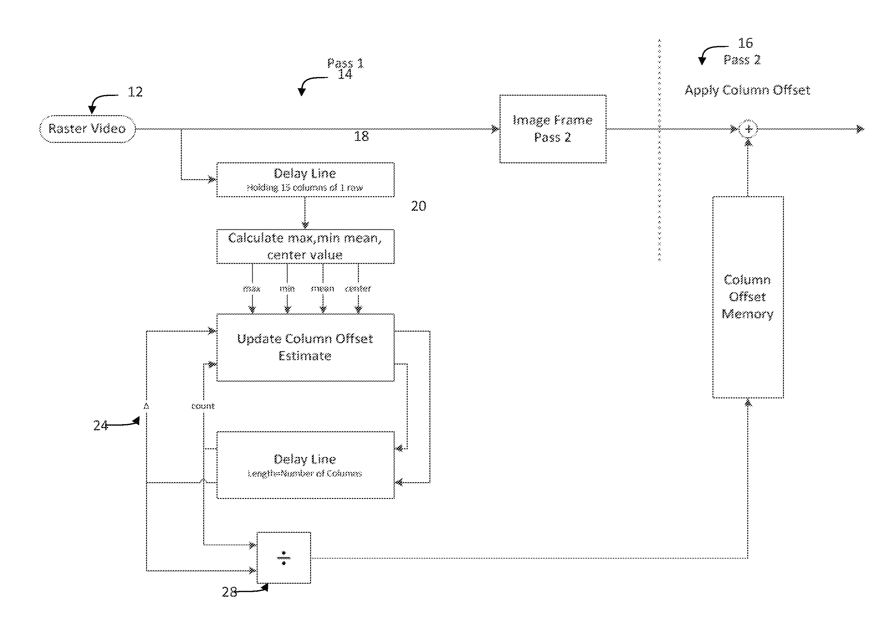
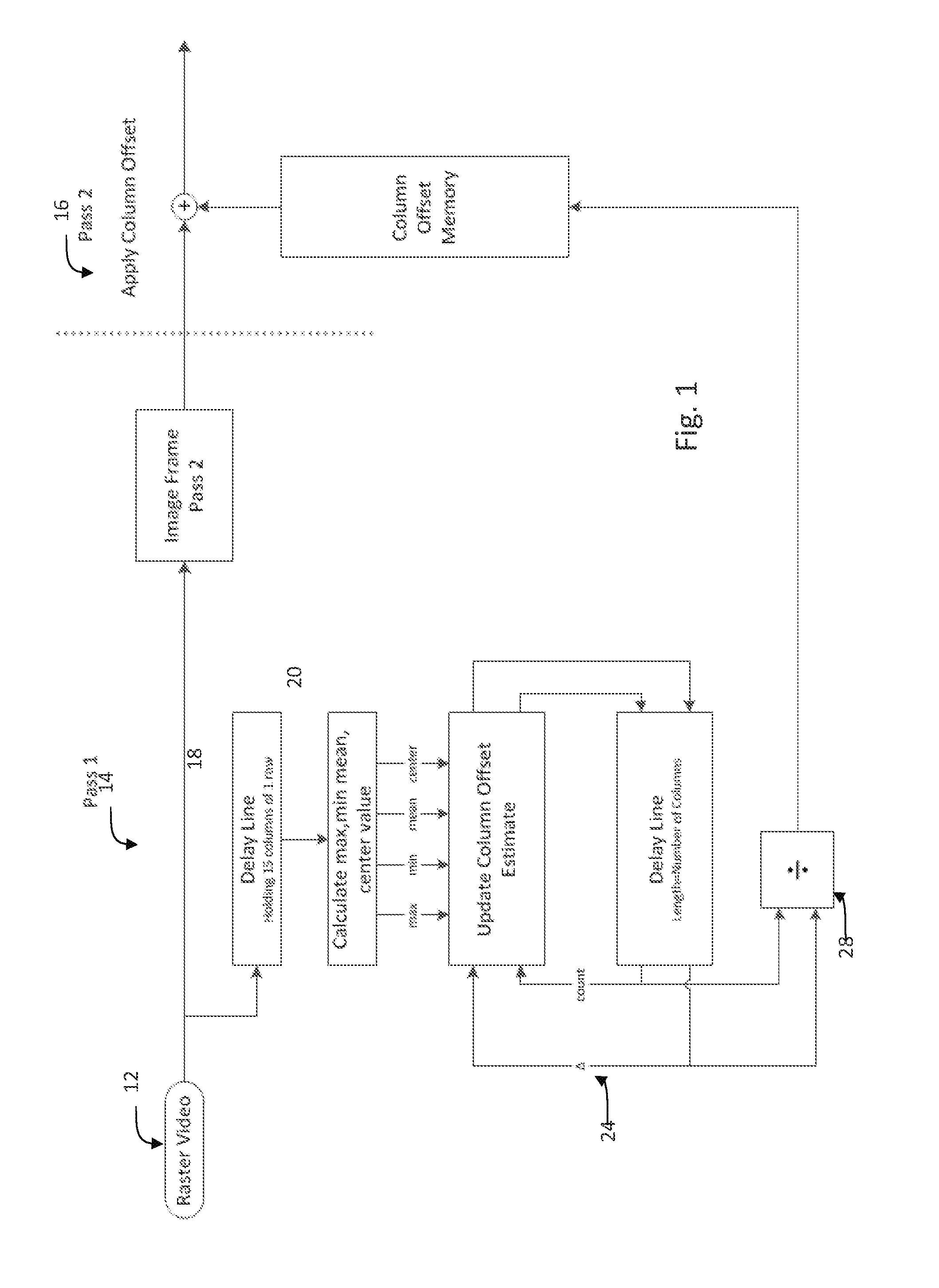
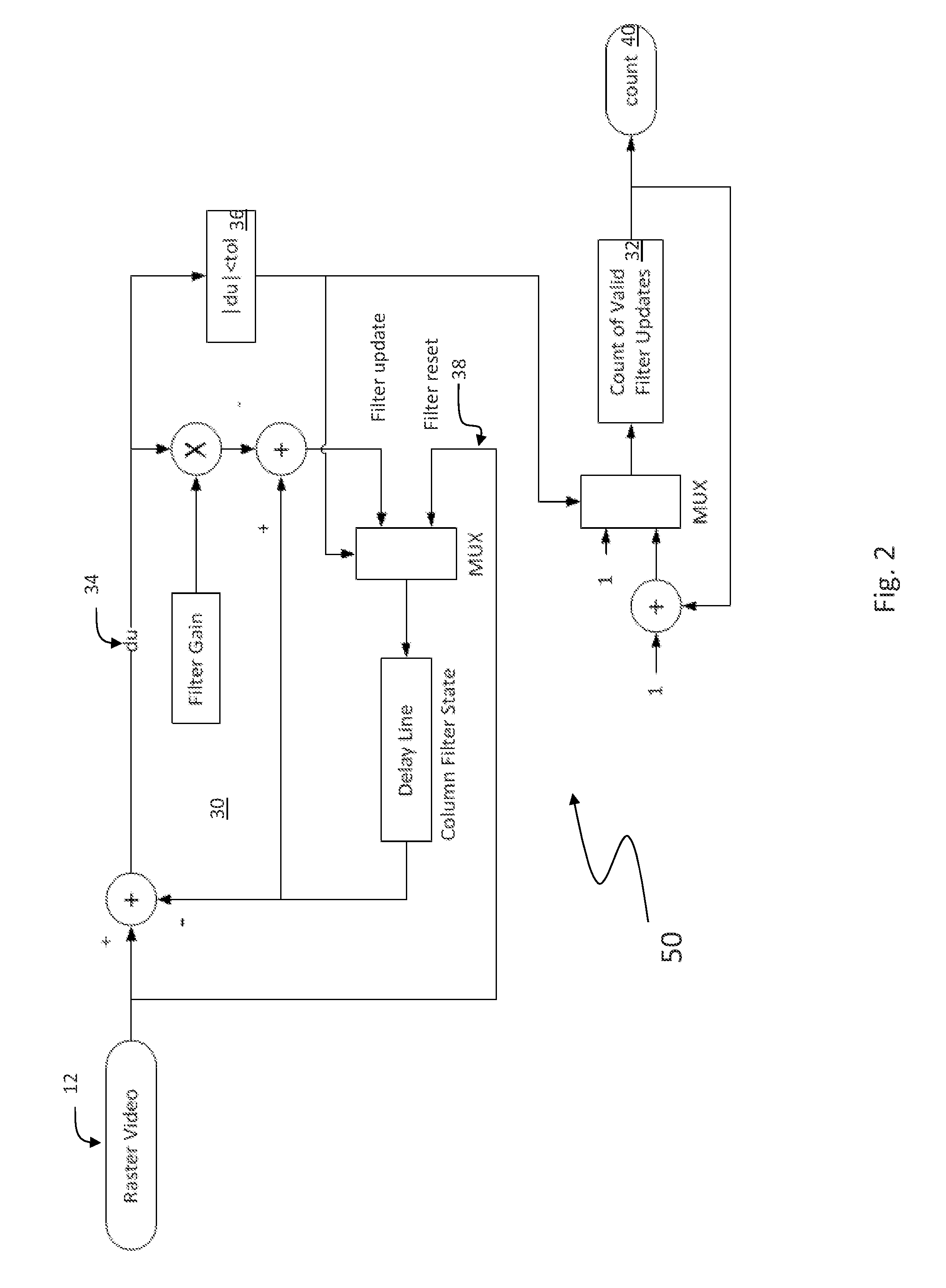
The present invention provides methods for reducing noise in an image. The first method reduces noise in a pixel group by identifying a homogeneous set of pixels near the subject pixel and calculating a pixel intensity correction by taking the difference between the homogeneous pixels and the subject pixel. The correction is then averaged over the pixel group to apply to the subject pixel. The second method removes column noise by identifying columns proximate to a subject column, calculating maximum, minimum, mean, and center column pixel intensity values, and adding the difference between the maximum and minimum to an accumulated offset estimate. The accumulated offset estimate is then divided by the number of columns to yield a column offset which is applied to reduce column noise. The third method filters columns of pixels through a low pass filter and calculates a row offset from average row differences of rows for which a count of valid filter updates exceed a preset threshold. The row offset is then updated the image to reduce row noise. These methods can improve image quality and reduce noise in various applications such as photography, video production, and medical imaging.

Problems solved by technology

One of the most common problems with detector array based imaging systems, especially those that use un-cooled arrays, is noise.
In such systems, minor hardware defects can cause a noise bias causing “blinking stripes” to appear along columns, rows, or both in the field of view (FOV).
These flashing stripes impede performance of the imaging system by partially obscuring viewed objects and, in a night vision goggle or weapon sight application, can be distracting and cause headaches for the user.
Unfortunately, because this noise is random, rather than fixed in time, it cannot be calibrated out of the image through the use of traditional offsets.

Method used


Image

  • Method for reducing row and column noise in imaging systems
  • Method for reducing row and column noise in imaging systems
  • Method for reducing row and column noise in imaging systems

Examples


Embodiment Construction

[0024]One embodiment of the present invention provides a system and method to remove noise from focal plane arrays (FPA). Two types of noise are addressed by the embodiments of the present invention: column noise and row noise. Column noise is the appearance of vertical streaks in imagery. The vertical streaks occur because the average light intensity level of each column in the array is different. This type of noise may occur in uncooled IR focal plane arrays and other area image detectors. The column intensity offsets of the array vary temporally and are also uncorrelated temporally so that these offsets cannot be removed by a factory calibration but are required to be corrected on the fly independently for each image frame. In order for the FPA to be used for live video, the column noise must be removed in real time and with a small enough processing delay so as not be noticeable by the viewer of the video. In order for the column noise reduction system to be used for portable vi...


PUM


Abstract

A method for the reduction of noise in an image including identifying neighboring pixel values in pixels proximate to a subject pixel; comparing the neighboring pixel values to a preset tolerance range; using neighboring pixel values within the tolerance range to calculate a pixel intensity correction value; and applying the pixel intensity value to the subject pixel.

Description

RELATED APPLICATIONS[0001]This application claims the benefit of U.S. Provisional Application No. 61 / 532,263 filed on Sep. 8, 2011. This application is herein incorporated by reference in its entirety for all purposes.FIELD OF THE INVENTION[0002]The present application relates to imaging systems and more particularly to noise reduction in imaging systems.BACKGROUND OF THE INVENTION[0003]One of the most common problems with detector array based imaging systems, especially those that use un-cooled arrays, is noise. In such systems, minor hardware defects can cause a noise bias causing “blinking stripes” to appear along columns, rows, or both in the field of view (FOV). These flashing stripes impede performance of the imaging system by partially obscuring viewed objects and, in a night vision goggle or weapon sight application, can be distracting and cause headaches for the user. Unfortunately, because this noise is random, rather than fixed in time, it cannot be calibrated out of the ...

Claims


Application Information

Patent Timeline
IPC IPC(8): G06T5/00G06T5/40
CPCG06T5/002G06T2207/20012G06T5/20G06T5/70G06T5/40G06T2207/20182H04N25/671
Inventor MENIKOFF, ARTHUR
Owner BAE SYST INFORMATION & ELECTRONICS SYST INTERGRATION INC
Learn More