Flexible lensed optical interconnect device for signal distribution

Active Publication Date: 2013-03-14
COMMSCOPE TECH LLC
View PDF9 Cites 77 Cited by
  • Summary
  • Abstract
  • Description
  • Claims
  • Application Information

AI Technical Summary

Problems solved by technology

Further, because the cassettes are hand-assembled, they are subject to human error and variability depending on operator skill and experience, especially with respect to improper fiber routing.
In addition, assembly of a fiber optic cassette involves time-consuming, in-process testing, especially for higher speed components.
With the channels now needing many more fibers, consolidation of these channels into larger fiber count trunks will be critical in the future as space inside data centers becomes more costly.
As a conseque

Method used


Image

  • Flexible lensed optical interconnect device for signal distribution
  • Flexible lensed optical interconnect device for signal distribution
  • Flexible lensed optical interconnect device for signal distribution

Examples


Embodiment Construction

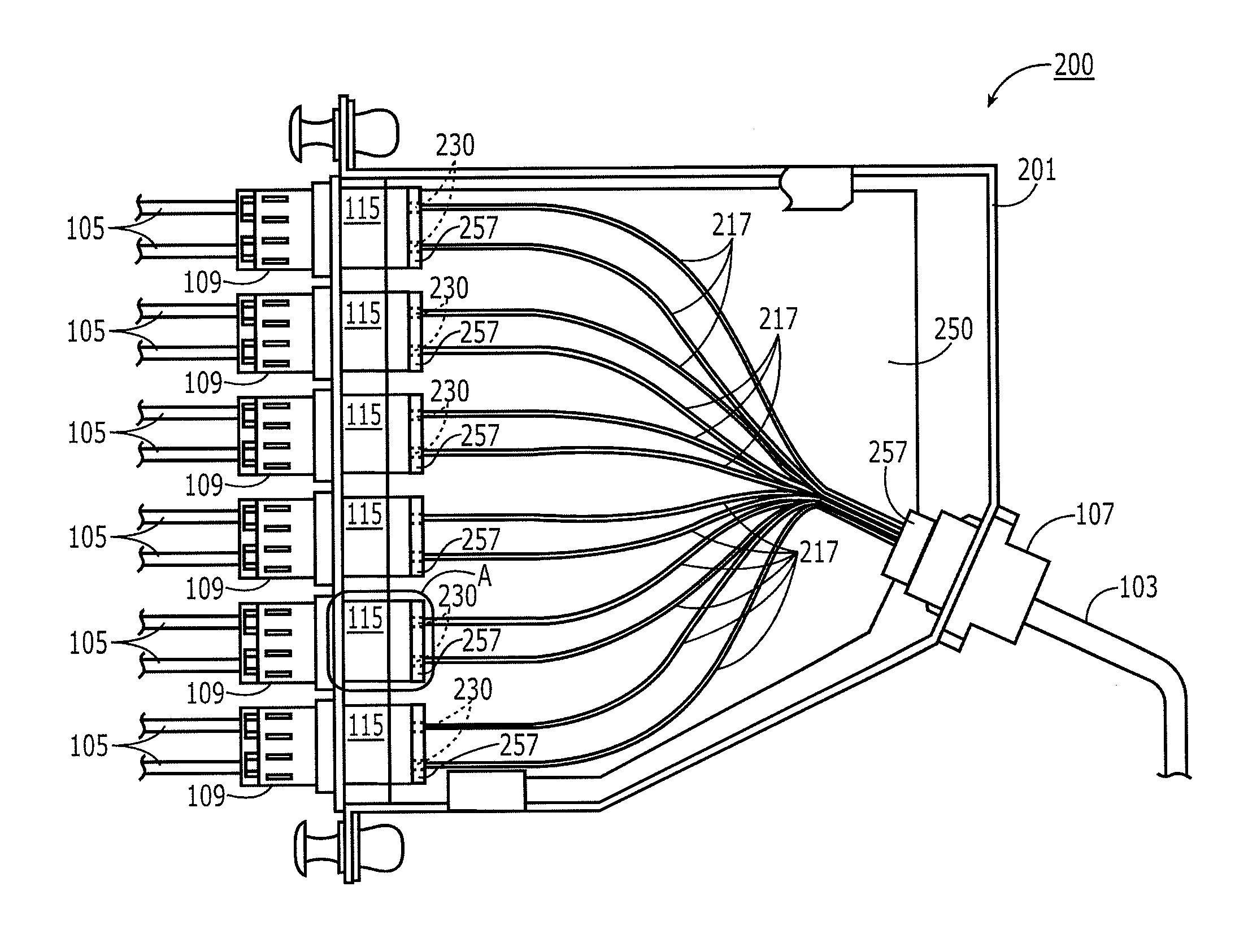
[0017]The present invention relates to a method and apparatus for interconnecting first and second optical components, such as optical cables or electro-optical devices in a cost-effective, flexible, and repeatable manner. The invention is particularly suitable in such applications as optical cassettes, patch cables, optical splitters, and patch panel interconnectors, zone distribution hardware, wall fixtures and the like.

[0018]The present invention involves the use of flexible optical circuits bearing at least one, but, more effectively, many optical fibers embedded in a flexible optical circuit substrate with a molded lens disposed at at least one end face of the one or more fibers. The lenses can be optically interfaced with external standard optical connectors (e.g., MPO, LC, ST, SC plugs) at the ends of cables or at the interfaces of electro-optical devices without the need for a conventional mating connector (e.g., MPO, LC, ST, SC receptacles). Rather, a connector on an optica...


PUM


Abstract

A method and device for interconnecting optical components, such as optical fibers and optical circuits, in a flexible, repeatable, and cost-effective manner. Two or more optical components are interconnected by a flexible optical circuit substrate bearing one or more embedded optical fibers with a lens at each end of each fiber. The flexible optical circuit may be incorporated into a housing bearing apertures for receiving optical connectors of the optical components that are to be interconnected with the device. The lensed ends of the fibers embedded in the flexible optical circuit are positioned adjacent to the apertures for optically connecting to the fibers within the connectors installed in the apertures without conventional mating connectors disposed inside the housing.

Description

FIELD OF THE INVENTION[0001]The invention pertains to fiber optic connectivity for high speed signal distribution.BACKGROUND OF THE INVENTION[0002]Fiber optic breakout cassettes are passive, optical components that connect fibers between sets of cables. Such cassettes usually provided transition between multi-fibered connectors, such as MPO type connectors with MT ferrules, and single or dual fiber connectors, such as LC or SC type connectors. A typical fiber optic breakout cassette of the prior art is illustrated in FIG. 1. The function of this particular exemplary cassette 100 is to distribute the signals between the twelve fibers contained in fiber optic cable 103 and six dual-fiber cables 105. For instance, in a practical case, each dual-fiber cables 105 comprises one transmit channel and one receive channel. Hence, six of the fibers in the twelve-fiber cable 103 transmit data into and through the cassette to one of the fibers in each of the six dual-fiber cables 105. The other ...

Claims


Application Information

Patent Timeline
IPC IPC(8): G02B6/30
CPCG02B6/32G02B6/4471G02B6/3608G02B6/3825G02B6/3612G02B6/3616G02B6/3897G02B6/4453
Inventor EBERLE, JR., JAMES JOSEPHBARRY, BRUCE ELTRINGHAM
Owner COMMSCOPE TECH LLC
Why Eureka
Try Eureka