
Historical Analysis of Battery Cells for Determining State of Health

a battery cell and historical analysis technology, applied in secondary cells servicing/maintenance, instruments, electrochemical generators, etc., can solve problems such as unbalanced battery pack system modules or battery cells, battery cells and battery pack system modules may experience different wear and use patterns, and battery system may not behave as desired

Active Publication Date: 2013-03-14
SOUTHWEST ELECTRONICS ENERGY CORP
View PDF2 Cites 53 Cited by
  • Summary
  • Abstract
  • Description
  • Claims
  • Application Information

AI Technical Summary

Benefits of technology

The patent describes a method and apparatus for monitoring and identifying faulty battery cells in a battery pack system. The method involves monitoring the voltage of each battery cell in real-time and counting the number of times it deviates from the average voltage of the other cells. When the deviation exceeds a threshold value, the battery cell is marked as faulty and a message is sent to the user. The system can also detect small shorts and larger shorts, and can disconnect the faulty battery cell from the system. The technical effect of this patent is to improve the reliability and performance of battery packs by identifying and addressing faulty battery cells in a timely manner.

Problems solved by technology

The battery system may not behave as desired when battery pack system modules are out of balance with each other or battery cells within a battery pack system module are out of balance with each other.
For example, an output voltage from and / or capacity in a battery system with unbalanced battery pack system modules or battery cells may be outside a desired range.
Battery cells and battery pack system modules may experience different wear and use patterns.
When battery cells and battery pack system modules experience different wear and use patterns they become more out of balance with other battery cells and battery pack system modules.
One cause may be differences in the age of the cells or modules.
This results because older cells or modules typically have lower capacity.
Another cause may be difference in the capacity of the cells or modules when they are manufactured.
Even when modules or cells are manufactured by the same supplier, the cells or modules used in a system may not be obtained from the same manufacturing lot of the supplier.
Cells or modules that experience different temperatures throughout operation may suffer different reductions in capacity.
Another cause may be differential power drain internal to a module.
A battery management system may have component variations or a normal current leakage paths resulting in balancing of a module due to internal power drain of the module.
A fifth cause may be differential physical damage to a cell or module.
Physical damage may reduce capacity or create internal shorts.
Another cause may be differential leakage of current internal or external to a cell or cells within a module.
Pack manufacturing defects are one cause for external differential leakage current.
Cell defects or damage are another cause for external differential leakage current.
For example, internal cell shorts may occur as a result of anode dendrites, separator dendrites, manufacture metal flake defects, weld splash defects, cell crush damage, excessive cell vibration, and / or shock.
These internal shorts may generate localized heat within the interior of a cell.
Even small intermittent shorts may cause lasting damage to a battery cell.
Although small intermittent shorts may burn themselves out, their occurrence may weaken the interior of the cell, which leads to more frequent and more severe internal shorts.
Over time, and with stresses of charging and discharging, multiple instances of internal shorts may eventually result in an internal short severe enough to cause a thermal run away event.
A thermal run away event is the release of a dangerous amount of energy that may destroy the cell within a very short time.
The released energy may damage equipment or injure operators.
However, internal shorts often occur without causing a detectable temperature increase around the battery cell.
Even though the temperature does not immediately rise, a thermal runaway event may nonetheless be building in the battery cell.
During a future charge cycle of the battery cells, battery cells coupled to the internally shorted battery cell may overcharge, increasing the likelihood of a thermal runaway event due to the additional stress on the otherwise-healthy battery cells.
The combination of the stressed healthy battery cells and the heat from the internally shorted battery cell may result in a thermal runaway event occurring that was originally undetectable by an external temperature sensor.

Method used


Image

  • Historical Analysis of Battery Cells for Determining State of Health
  • Historical Analysis of Battery Cells for Determining State of Health
  • Historical Analysis of Battery Cells for Determining State of Health

Examples


Embodiment Construction

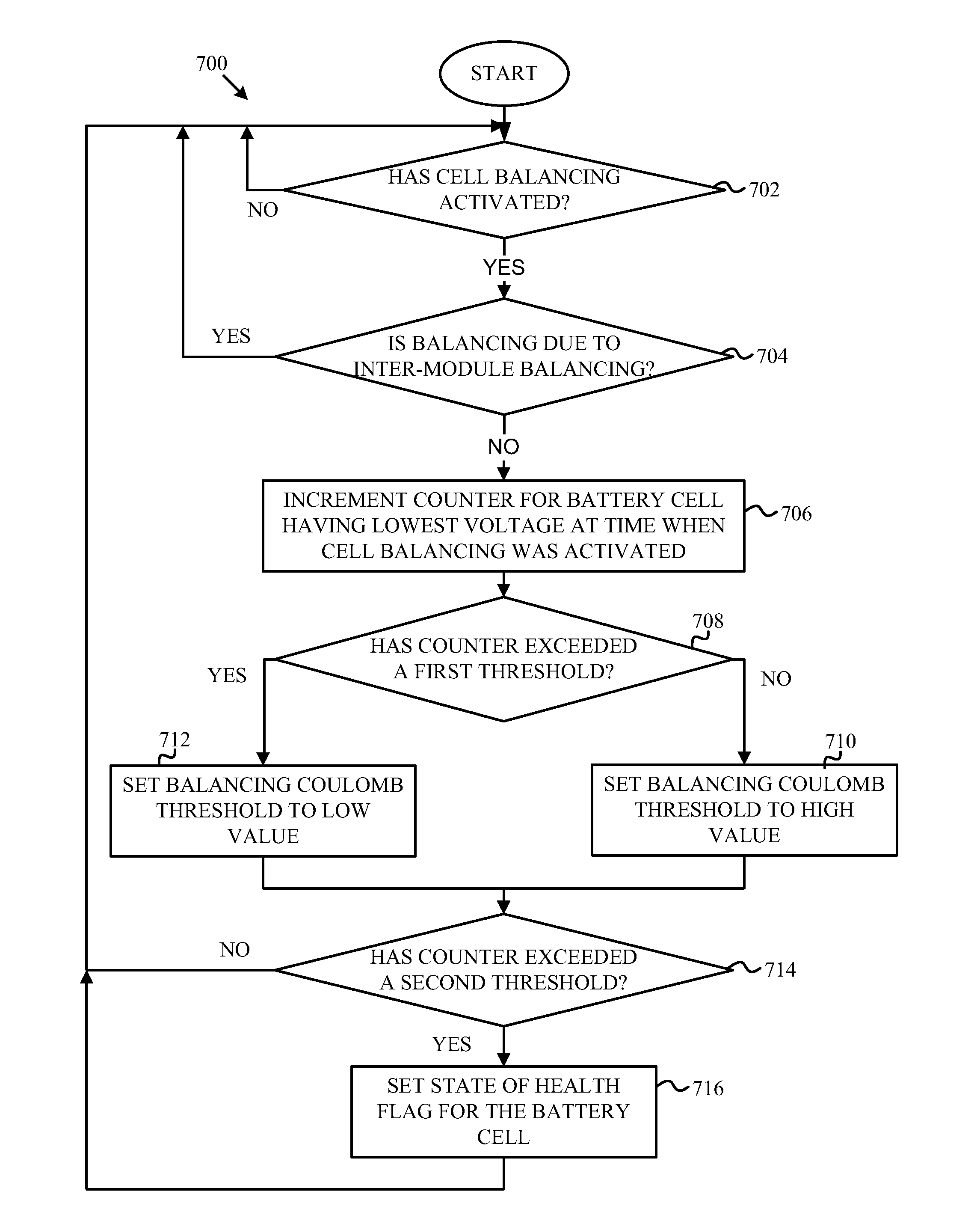
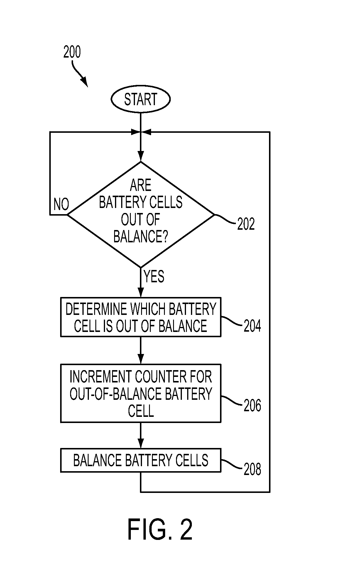
[0037]Although an external temperature monitor may be insufficient to detect a thermal run away event before it occurs, other methods may be used to detect internal shorts in battery cells or modules. A battery cell with internal shorts may be balanced more frequently or less frequently than other battery cells. For example, when an internal cell short causes a current drain the battery cell discharges faster causing the balancing circuits to direct differential current to respond to the shorted battery cell. A balancing circuit or an external monitor to the balancing circuit, may track the number of times a battery cell is balanced and determine that a battery cell has an internal short before a thermal run away event occurs. The circuit or monitor may determine the battery cell is being excessively balanced by implementing threshold detection such as when a count exceeds a threshold, implementing an algorithm to detect unusual balancing behavior over time, and / or implementing a di...


PUM


Abstract

Battery cells may be monitored and a historical profile of the battery generated. The historical profile may be used to analyze a state-of-health of the battery cell. For example, the historical profile may be used to determine when a battery cell has developed an internal short that creates a safety hazard. The historical profile may include a count of the number of times the battery cell was out of balance and a count of the number of Coulombs the battery cell was out of balance. The number of Coulombs may be counted for a window of time. When the number of Coulombs exceeds a Coulomb threshold, a state-of-health flag may be set for the battery cell. The Coulomb threshold may be adjusted based, in part, on the counted number of times the battery cell is out of balance.

Description

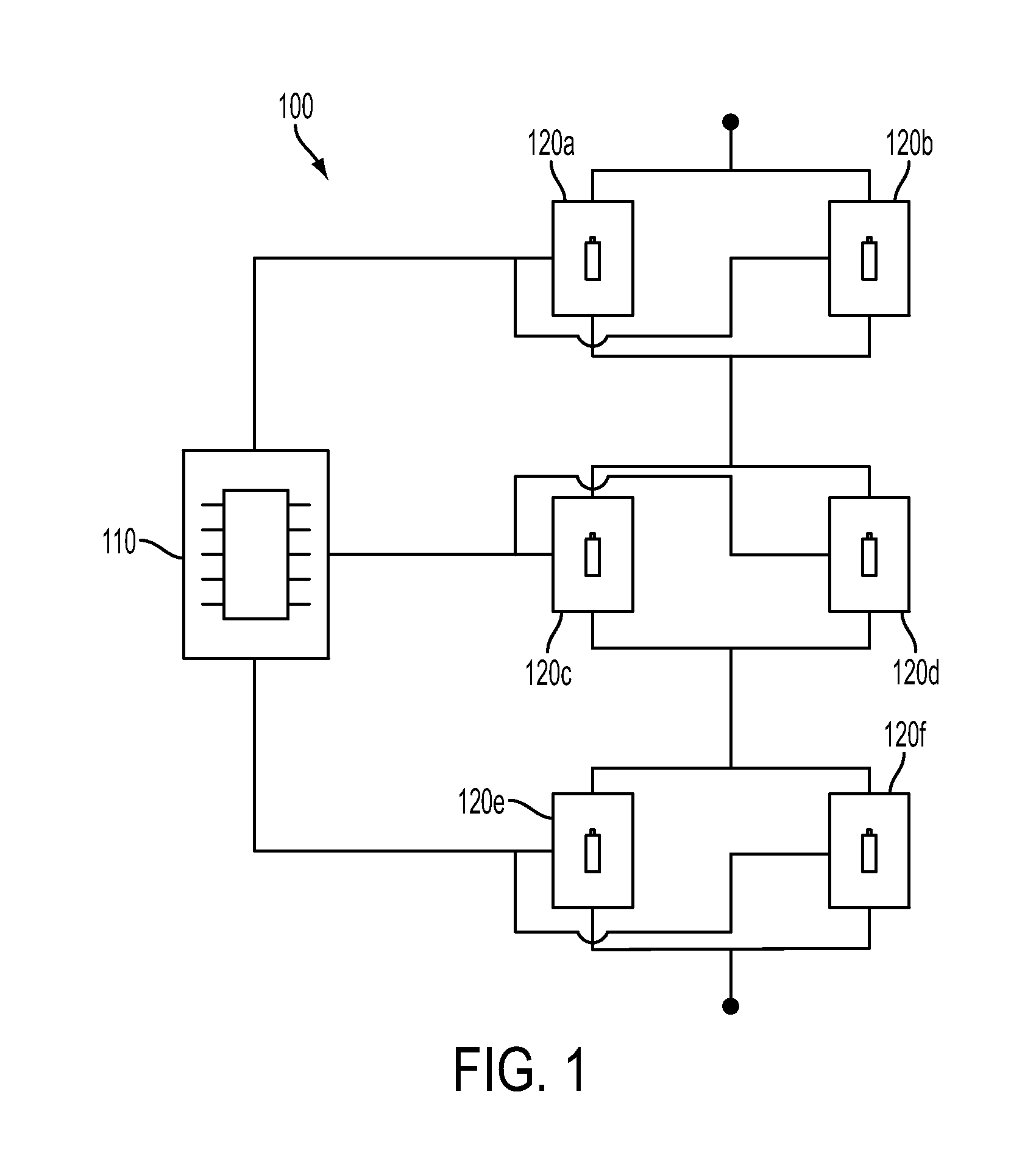
TECHNICAL FIELD[0001]The present disclosure is related to rechargeable batteries. More specifically, the present disclosure is related to fault detection in rechargeable batteries.BACKGROUND[0002]A device powered by rechargeable batteries may include several battery cells to achieve voltage and / or current levels used by the device. For example, if a rechargeable battery cell has a nominal output voltage of 1 Volt, a device having a 2 Volt operational level may include two battery cells coupled in series. In another example, if a rechargeable battery cell has a nominal output current of 100 milliamps, a device having a 400 milliamp operational level may include four battery cells coupled in parallel. Battery cells coupled in parallel and series may be combined to reach the desired operational voltage and current levels of the device.[0003]The battery cells may be grouped with circuitry for balancing the charge levels in the battery cells to form a battery pack system module. Multiple...

Claims


Application Information

Patent Timeline
IPC IPC(8): H01M10/48
CPCH01M10/42G01R31/3679G01R31/3648H01M2010/4271G01R31/392
Inventor WHITE, DAVID A.BENCKENSTEIN, JR., CLAUDE L.
Owner SOUTHWEST ELECTRONICS ENERGY CORP
Learn More