Micromachined gyroscope including a guided mass system

a micro-machined gyroscope and guided mass technology, applied in the direction of acceleration measurement using interia force, turn-sensitive devices, instruments, etc., can solve the problems of increasing the cost of production, so as to achieve the effect of reducing cost and power

Active Publication Date: 2013-03-21
INVENSENSE
View PDF34 Cites 53 Cited by
  • Summary
  • Abstract
  • Description
  • Claims
  • Application Information

AI Technical Summary

Benefits of technology

[0010]A method and system in accordance with the present invention provides a mechanical structure that oscillates at one frequency and is capable of sensing angular rate about multiple axes. One drive motion requires only one drive circuit, which low

Problems solved by technology

Out-of-plane drive tends to be less efficient than in-plane drive, requires additional fabrication steps, and is limited by nonlinearities.
Forming a cavity under the proof-mass requires additional fabrication steps and increases cost.
Because the proof-mass oscillates out-of-plane, the electrostatic force is nonlinear wh

Method used


Image

  • Micromachined gyroscope including a guided mass system
  • Micromachined gyroscope including a guided mass system
  • Micromachined gyroscope including a guided mass system

Examples


second embodiment

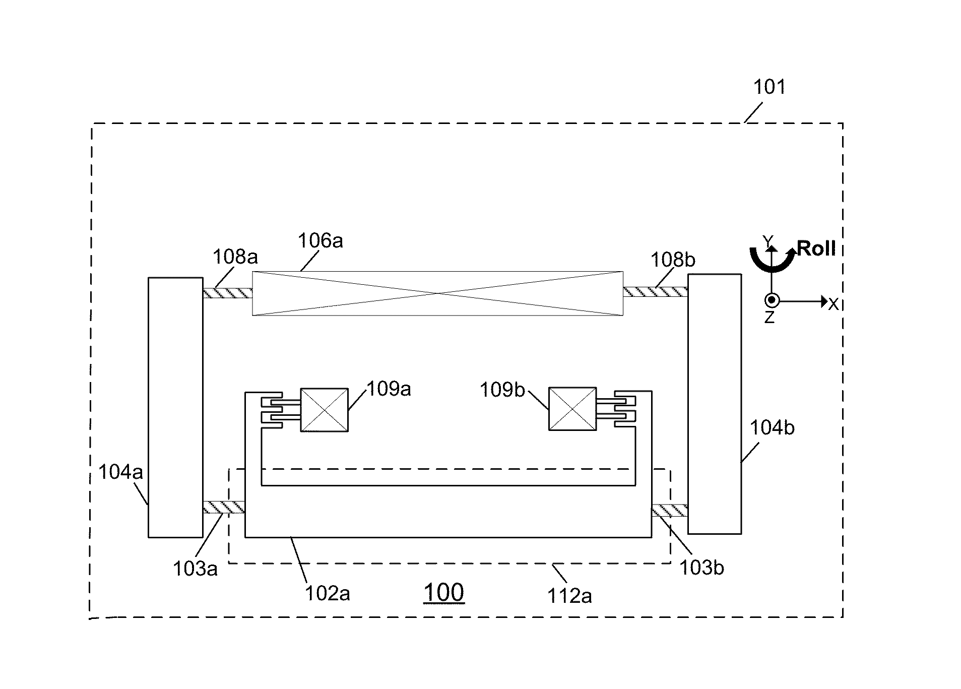
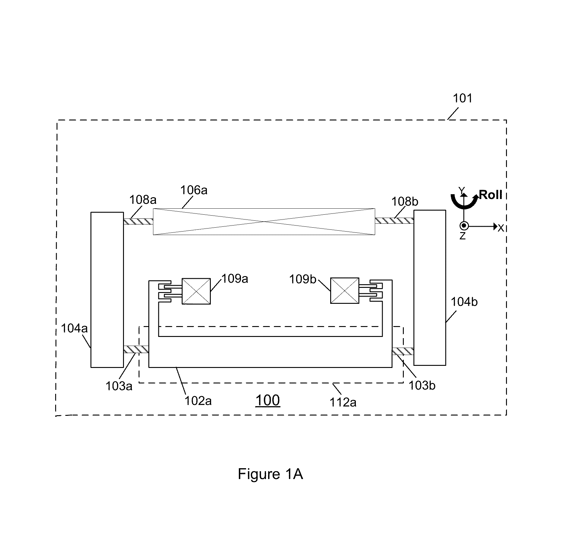
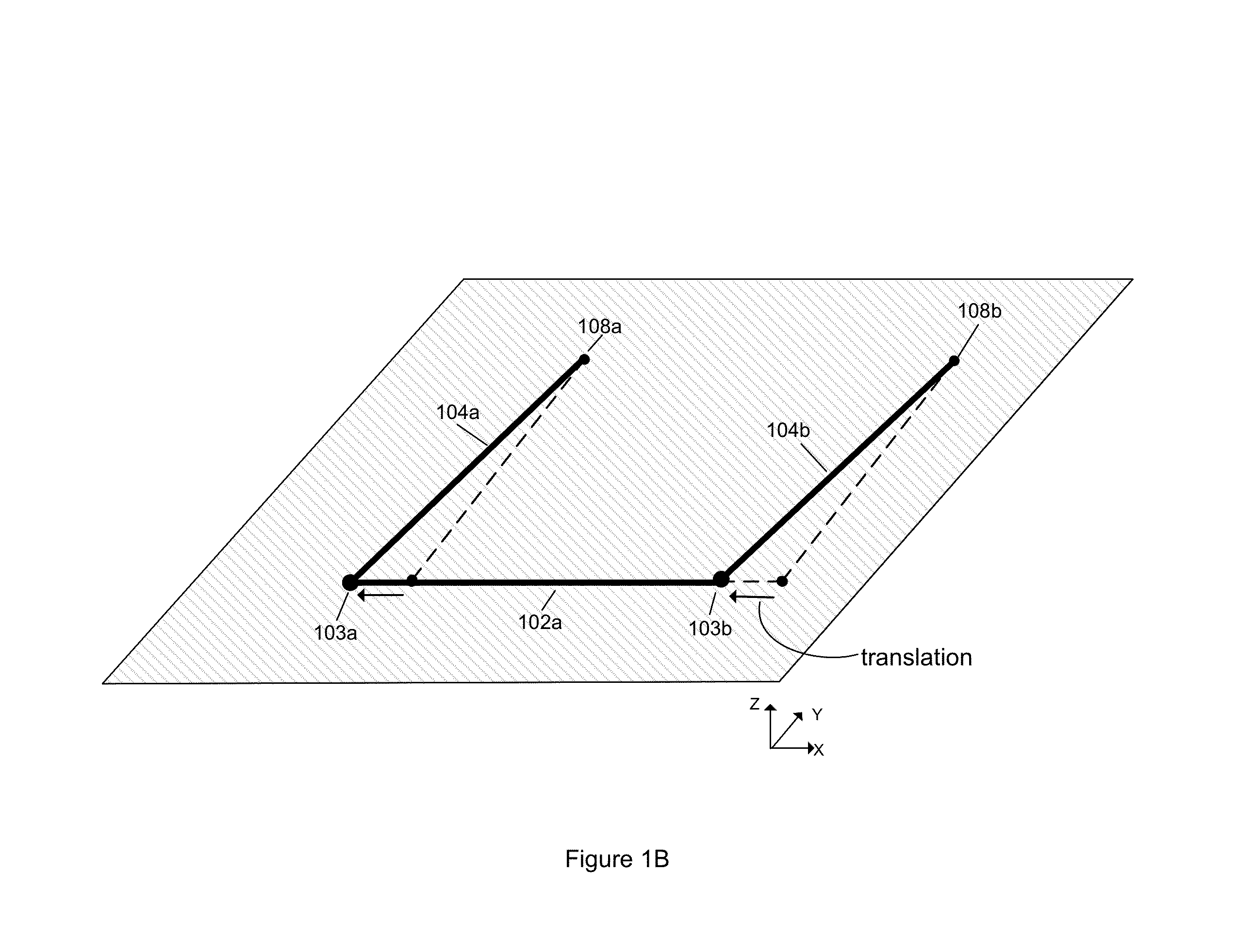
[0039]FIG. 6 illustrates a dual-axis gyroscope comprising a guided mass system 600 surrounded by a stress relief frame 402 in accordance with the present invention The guided mass system 600 comprises a symmetric guided mass system 200 coupled to a pitch proof-mass 650a. The stress relief frame 402 is connected to the guiding arms 104a and 104b via springs 108a and 108b and surrounds the symmetric guided mass system 200.

[0040]The pitch proof-mass 650a is flexibly connected to the two roll proof-masses 102a and 102b via springs 652a and 652b. Springs 652a and 652b are torsionally compliant such that pitch proof-mass 650a can rotate out-of-plane about a pitch sense axis in the Y-direction. Springs 652a and 652b are compliant in-plane such that when the roll proof-masses 102a and 102b are driven anti-phase in the X-direction; the pitch proof-mass 650a rotates in-plane about an axis in the Z-direction.

[0041]Angular velocity about the pitch-input axis will cause Coriolis forces to act on...

third embodiment

[0042]FIG. 7 illustrates a dual-axis gyroscope comprising a guided mass system 700 in accordance with the present invention. The guided mass system 700 comprises a symmetric guided mass system 200 coupled to two yaw proof masses 518a and 518b. The yaw proof-masses 518a and 518b are flexibly connected to the roll proof-masses 102a and 102b via springs 520a-d and 520e-h respectively. When the guided mass system 700 is driven, the yaw proof-masses 518a and 518b also translate anti-phase in the X-direction.

[0043]Angular velocity about the yaw-input axis will cause Coriolis forces to act on the yaw proof-masses 518a and 518b resulting in motion of the yaw proof-masses 518a and 518b anti-phase along the Y-direction. The amplitude of the motion of the yaw proof-masses along the Y-direction is proportional to the angular velocity. Transducers 522a and 522b are used to sense the motion of the respective yaw proof masses 518a and 518b along the Y-direction.

[0044]FIG. 8 illustrates an embodime...


PUM


Abstract

A gyroscope is disclosed. The gyroscope comprises a substrate; and a guided mass system. The guided mass system comprises proof-mass and guiding arm. The proof-mass and the guiding arm are disposed in a plane parallel to the substrate. The proof-mass is coupled to the guiding arm. The guiding arm is also coupled to the substrate through a spring. The guiding arm allows motion of the proof-mass to a first direction in the plane. The guiding arm and the proof-mass rotate about a first sense axis. The first sense axis is in the plane and parallel to the first direction. The gyroscope includes an actuator for vibrating the proof-mass in the first direction. The gyroscope also includes a transducer for sensing motion of the proof-mass-normal to the plane in response to angular velocity about a first input axis that is in the plane and orthogonal to the first direction.

Description

FIELD OF THE INVENTION[0001]The present invention relates generally to angular velocity sensors and more particularly relates to angular velocity sensors that include guided mass systems.BACKGROUND OF THE INVENTION[0002]Sensing of angular velocity is frequently performed using vibratory rate gyroscopes. Vibratory rate gyroscopes broadly function by driving the sensor into a first motion and measuring a second motion of the sensor that is responsive to both the first motion and the angular velocity to be sensed.[0003]Frequently, a mass, usually referred to as a proof mass, within the sensor is driven into oscillation by an actuator. Rotation of the sensor imparts a Coriolis force to the oscillating mass that is proportional to the angular velocity (or rotation rate), and depends on the orientation of the angular velocity vector with respect to the velocity vector of the proof mass. The Coriolis force, the angular velocity vector, and the proof-mass velocity vector are mutually orthog...

Claims


Application Information

Patent Timeline
IPC IPC(8): G01C19/56
CPCG01C19/574G01C19/5733G01C19/5755G01C19/5712G01C19/5747G01C19/5762
Inventor SEEGER, JOSEPHANAC, OZAN
Owner INVENSENSE
Why Eureka
Try Eureka