
Method and apparatus for providing complimentary state retention

a state information and complementary technology, applied in the field of circuits and methods to backup state information, can solve the problems of consuming an inordinate amount of time, affecting the efficiency of state saving techniques, and defeating the purpose of power gating in an integrated circui

Active Publication Date: 2013-03-21
ADVANCED MICRO DEVICES INC
View PDF4 Cites 28 Cited by
  • Summary
  • Abstract
  • Description
  • Claims
  • Application Information

AI Technical Summary

Benefits of technology

The patent text describes a method and apparatus for saving the state of a processor or logic chip when power is to be shut down or when the chip is to be powered off. The technical effect of this patent is to provide a more efficient and effective way to save and restore the state of a chip, allowing for power gating and energy conservation in mobile devices and other non-mobile devices.

Problems solved by technology

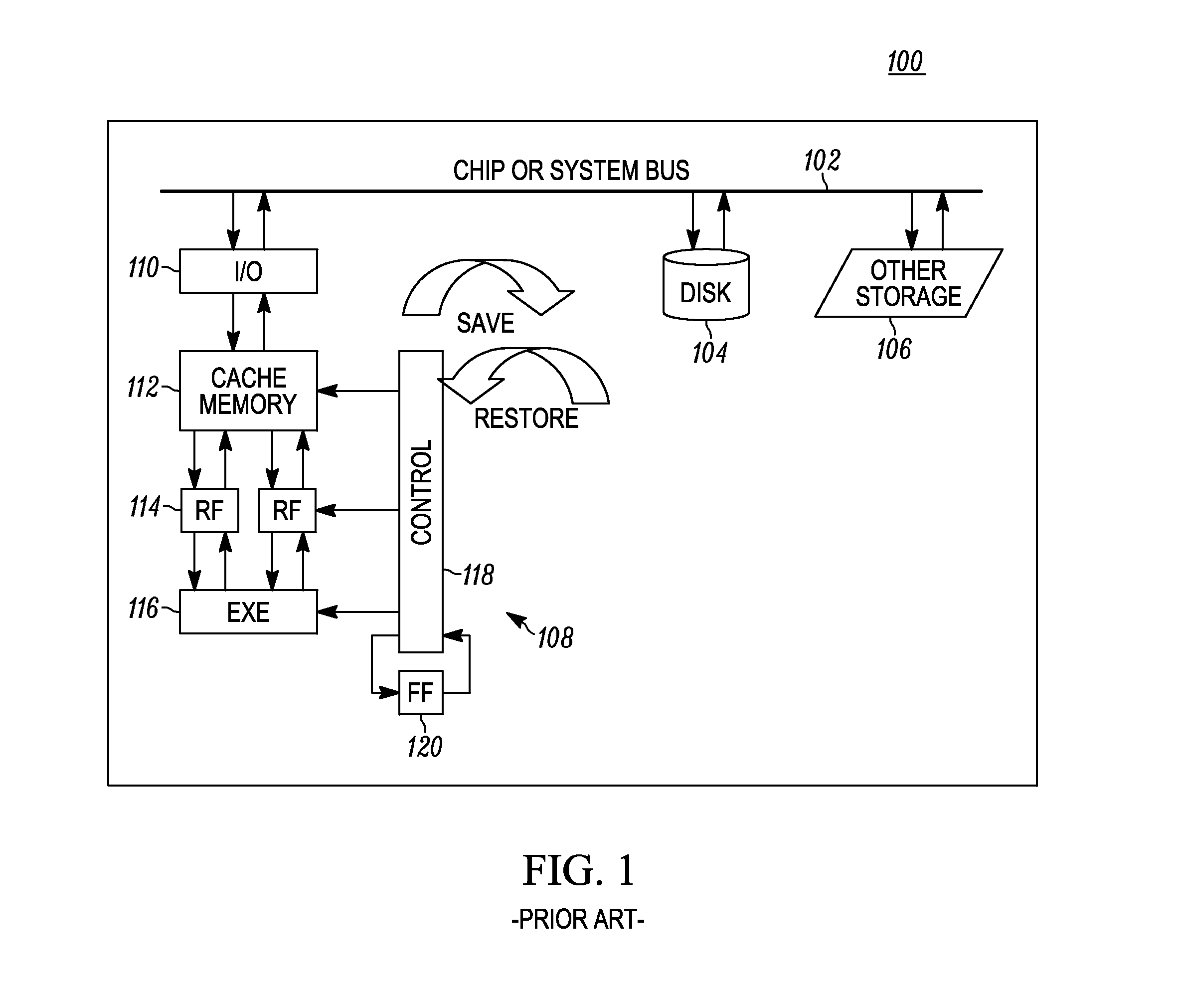
Saving the state of the processor can involve the tedious process of reading all of the architected states of the chip (or part of the chip) that is to be powered off and saved out to a section of the chip not to be powered off or power gated.
The scan chains may typically operate at a low frequency such as 100 MHz and typically scan out state data in a serialized fashion which can take an inordinate amount of time.
Such state saving techniques can require significant amounts of power to save and restore the state of entire sections of a chip, the entire chip or system.
This can defeat the purpose of power gating in an integrated circuit which allows the reduction or removal of power from subsections or portions of the chip to save power when they are not in use or otherwise slow down the operation to conserve power.
This results in additional leakage current from the many shadow flip-flops that are employed to save state, drawing unnecessary power and adding unnecessary temperature increases.
A drawback with such an approach includes that the design complexity with the separate power supply.
In addition, the circuitry including the retention state circuits typically continue to draw power during power down mode.
However, the extra power supply design results in additional costs, additional metal tracks and design effort.
In addition, the circuitry that is left powered on typically continue to consume power.
However, such approaches can significantly lengthen the required time for entering and exiting powered down modes.
Other disadvantages will be recognized by those of ordinary skill in the art.

Method used


Image

  • Method and apparatus for providing complimentary state retention
  • Method and apparatus for providing complimentary state retention
  • Method and apparatus for providing complimentary state retention

Examples


Embodiment Construction

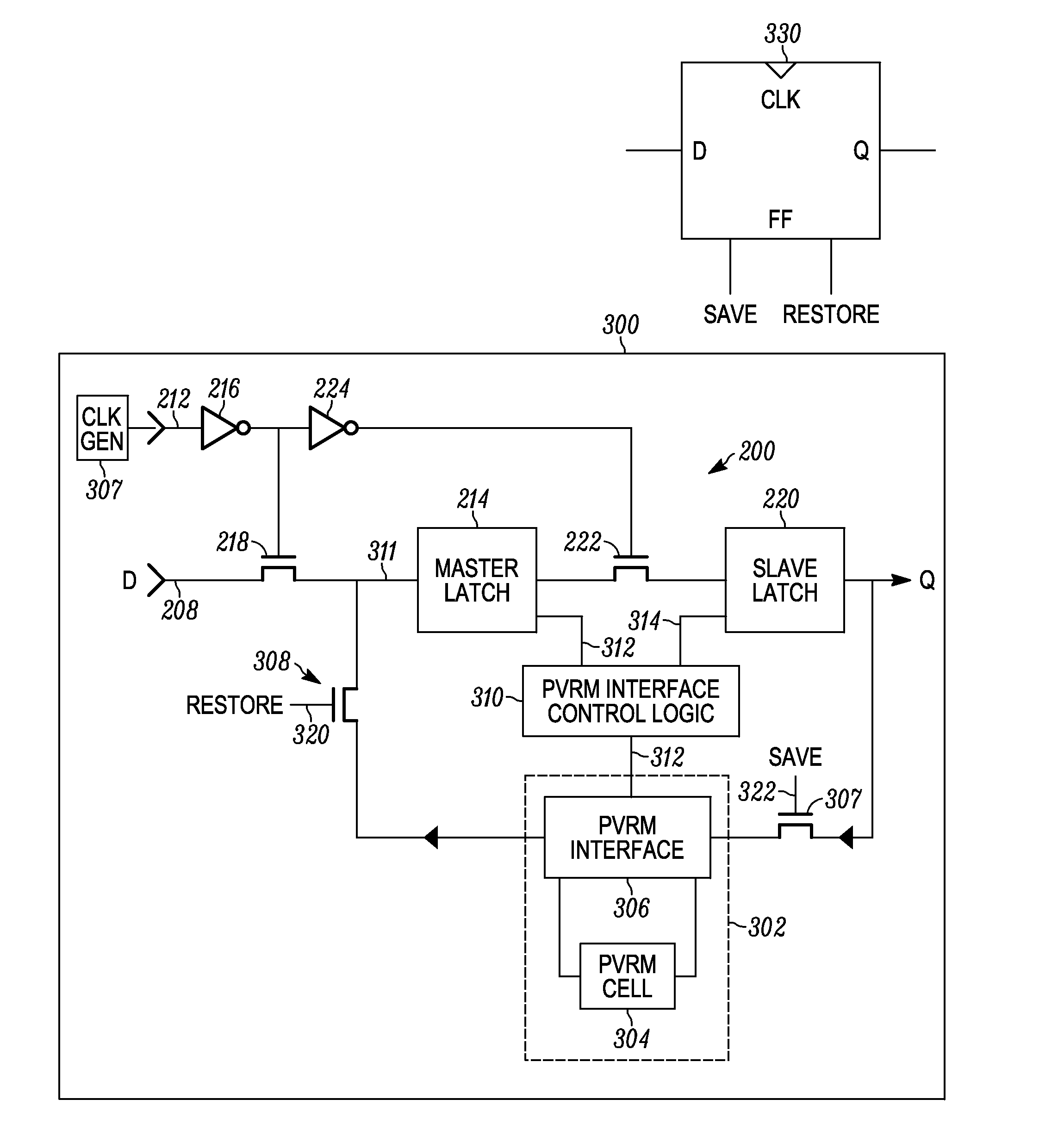
[0022]Briefly, a method, integrated circuit and apparatus are operative to control a plurality of passive variable resistance memory cells to store complimentary state information from at least one active memory circuit, such as a flop, latch, or any other suitable state generation circuit. The method, apparatus and integrated circuit may be operative to control the plurality of passive variable resistance memory cells to also restore the stored complimentary state information for the at least one active memory.

[0023]In one example, the at least one variable resistance state retention circuit includes at least one variable resistance cross coupled configured state retention circuit that includes a plurality of passive variable resistance memory (PVRM) cells in a cross coupled configuration. Control logic controls the PVRM cells to save complimentary state information from at least one active memory circuit. The control logic is also operative to restore the stored state information ...


PUM


Abstract

A method, integrated circuit and apparatus are operative to control a plurality of passive variable resistance memory cells to store complimentary state information from at least one active memory circuit, such as a flop, latch, or any other suitable state generation circuit. The method, apparatus and integrated circuit may be operative to control the plurality of passive variable resistance memory cells to also restore the stored complimentary state information for the at least one active memory.

Description

RELATED APPLICATIONS[0001]This application is a continuation-in-part to co-pending non-provisional application Ser. No. 13 / 561,547, filed on Jul. 30, 2012, having inventors Donald R. Weiss et al., titled “METHOD AND APPARATUS FOR DIRECT BACKUP OF MEMORY CIRCUIT”, owned by instant assignee and incorporated herein by reference, which claims priority to provisional application Ser. No. 61 / 535,730, filed on Sep. 16, 2011, having inventors Don R. Weiss et al., titled “METHOD AND APPARATUS FOR DIRECT BACKUP OF MEMORY CIRCUIT”, which is related to co-pending Provisional Application Ser. No. 61 / 535,733, filed on Sep. 16, 2011, having inventors David Mayhew et al., titled “METHOD AND APPARATUS FOR CONTROLLING STATE INFORMATION RETENTION IN AN APPARATUS”, and incorporated herein by reference.BACKGROUND OF THE INVENTION[0002]The disclosure relates generally to circuits and methods to backup state information in integrated circuits and more particularly to circuits and methods that save the sta...

Claims


Application Information

Patent Timeline
IPC IPC(8): G06T1/60H01L21/8239G11C11/34
CPCG11C13/0004G11C13/0007G11C13/0033G11C14/0081G11C14/009G11C2213/77G11C13/0061
Inventor WUU, JOHN J.WEISS, DONALD R.
Owner ADVANCED MICRO DEVICES INC
Learn More