
Stochastic synapse memory element with spike-timing dependent plasticity (STDP)

a memory element and plasticity technology, applied in the field of memory devices, can solve the problems of inefficiency of programmable electronic machines by a factor of one million to one billion, limited utility of electronic machines in complex environments, and inability to adapt to the needs of users

Inactive Publication Date: 2011-07-12
INT BUSINESS MASCH CORP
View PDF10 Cites 27 Cited by
  • Summary
  • Abstract
  • Description
  • Claims
  • Application Information

AI Technical Summary

Problems solved by technology

Owing both to limitations in hardware and architecture, such electronic machines are of limited utility in complex, real-world environments, which demand an intelligence that has not yet been captured in an algorithmic-computational paradigm.
As compared to biological systems, for example, such programmable electronic machines are less efficient by a factor of one million to one billion in complex, real-world environments.

Method used


Image

  • Stochastic synapse memory element with spike-timing dependent plasticity (STDP)
  • Stochastic synapse memory element with spike-timing dependent plasticity (STDP)
  • Stochastic synapse memory element with spike-timing dependent plasticity (STDP)

Examples


Embodiment Construction

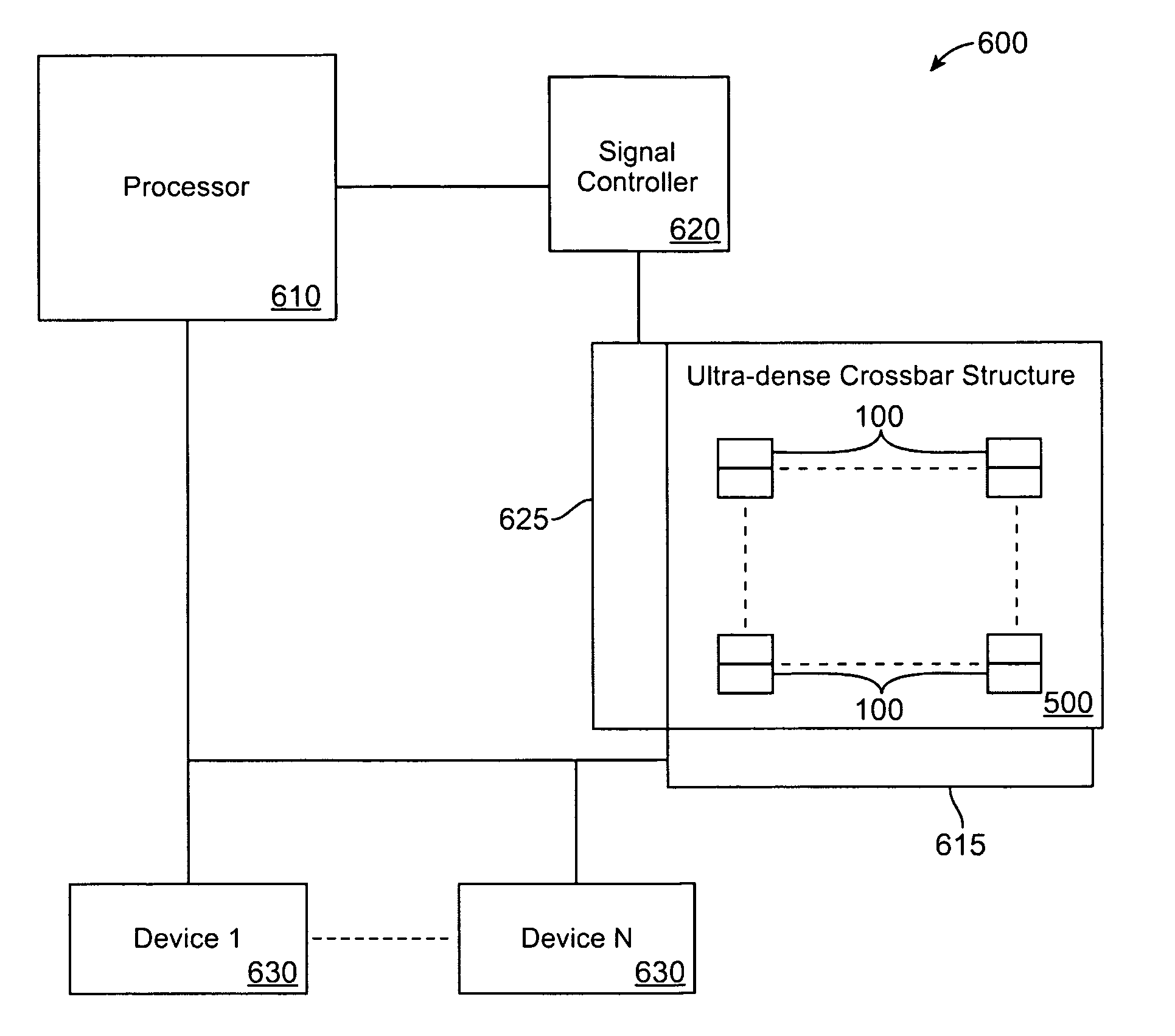
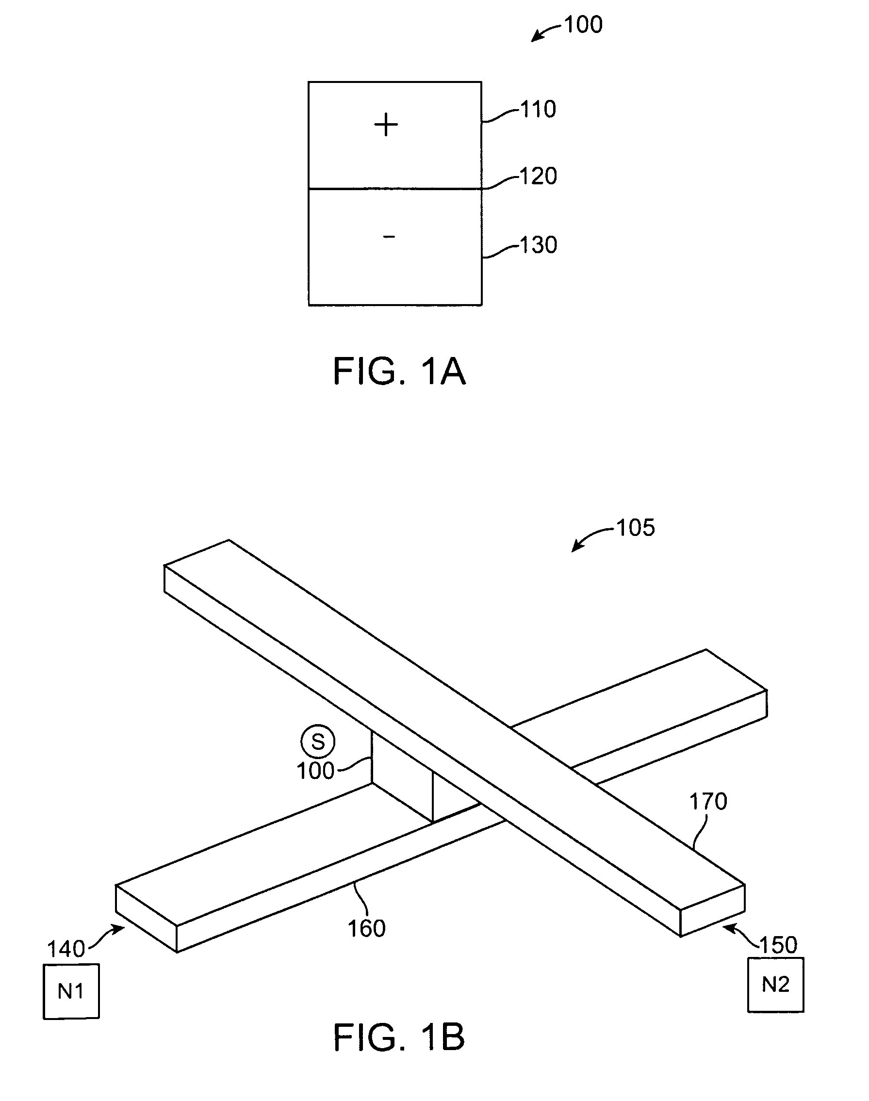
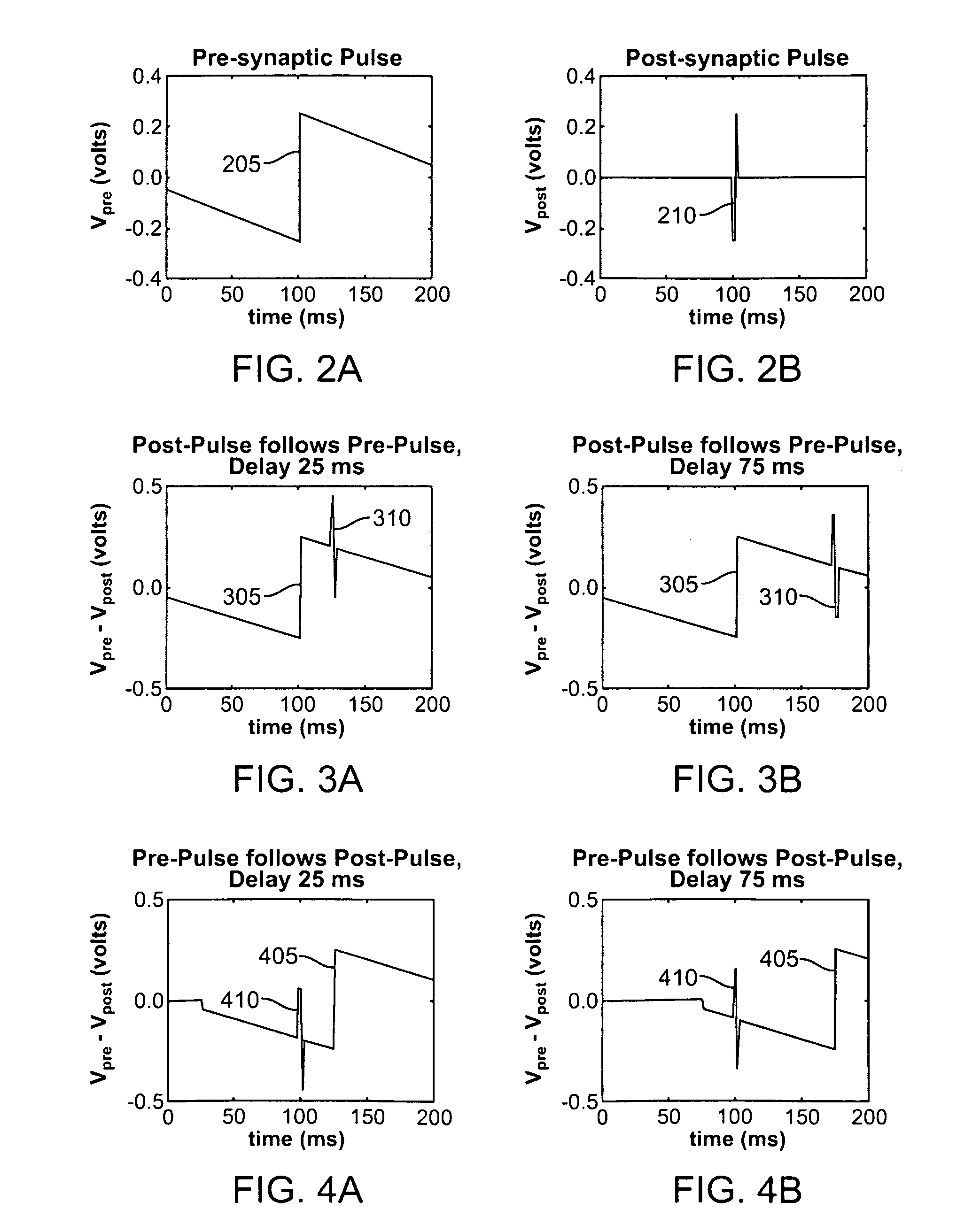
[0026]The following description is made for the purpose of illustrating the general principles of the invention and is not meant to limit the inventive concepts claimed herein. Further, particular features described herein can be used in combination with other described features in each of the various possible combinations and permutations. Unless otherwise specifically defined herein, all terms are to be given their broadest possible interpretation including meanings implied from the specification, as well as meanings understood by those skilled in the art and / or as defined in dictionaries, treatises, etc. The description may disclose several preferred embodiments for bi-polar memory-switching elements, including nano-scale memory array resources, as well as operation and / or component parts thereof. While the following description will be described in terms of memory synaptronic devices for clarity and placing the invention in context, it should be kept in mind that the teachings h...


PUM


Abstract

An active memory element is provided. A bipolar memory two-terminal element includes polarity-dependent switching. A probability of switching of the bi-polar memory element between a first state and a second state decays exponentially based on time delay and a difference between received signals at the two terminals and a switching threshold magnitude.

Description

GOVERNMENT RIGHTS[0001]This invention was made with United States Government support under Agreement No. HR0011-09-C-0002 awarded by Defense Advanced Research Projects Agency (DARPA). The government has certain rights in the invention.BACKGROUND[0002]1. Field of the Invention[0003]The present invention relates generally to memory devices, and more specifically, to bi-polar memory switching elements.[0004]2. Description of the Related Art[0005]Modern electronics has evolved through a series of major hardware developments such as transistors, integrated circuits, memories, and microprocessors. This has led to ubiquitous programmable electronic machines. Owing both to limitations in hardware and architecture, such electronic machines are of limited utility in complex, real-world environments, which demand an intelligence that has not yet been captured in an algorithmic-computational paradigm. As compared to biological systems, for example, such programmable electronic machines are less...

Claims


Application Information

Patent Timeline
Patent Type & Authority Patents(United States)
IPC IPC(8): G11C11/34
CPCG11C11/16G11C11/54G06N3/0635G06N3/049G11C13/0007G11C11/1659G11C11/1675G06N3/065
Inventor MODHA, DHARMENDRA S.PARKIN, STUART S. P.
Owner INT BUSINESS MASCH CORP
Learn More