Method for improving view angle of LCD and LCD

a liquid crystal display and view angle technology, applied in the field of liquid crystal displaying, can solve the problems of poor displaying effect of 3d image, increase the percentage of false image, and reduce the width of original black photoresist, so as to improve the aperture ratio, improve the view angle of the lcd, and reduce the width of the original black photoresist

Inactive Publication Date: 2013-03-21
TCL CHINA STAR OPTOELECTRONICS TECH CO LTD
View PDF5 Cites 6 Cited by
  • Summary
  • Abstract
  • Description
  • Claims
  • Application Information

AI Technical Summary

Benefits of technology

[0006]A primary objective of the present invention is to provide a method for improving a view angle of an LCD that can effectively improve the view angle of the LCD.
[0020]According to the present invention, a black masking unit is disposed on a back surface of the glass substrate to block light of the false image, so the view angle of the LCD can be improved; moreover, as this structure can reduce the width of the original black photoresist, the aperture ratio is improved. Additionally, because the black photoresist has a small width in the LCD of the present invention, error tolerance during assembly of the quarter-wave phase difference plate can be improved, thus reducing the reject ratio.

Problems solved by technology

However, when the user looks at the LCD from above or from below, an image from right-eye pixels will pass through the phase-difference plate in front of the left-eye pixels, so the image from the right-eye pixels that otherwise should be blocked by the eyeglass will be seen by the left eye to cause a false image.
As the user looks at the LCD at a larger view angle, the percentage of the false image becomes greater and the displaying effect of the 3D image becomes poorer.
Usually, in the 3D display, the 3D image will become unclear or the user will feel uncomfortable when the false image accounts for 7% of the correct image.
However, this leads to a decrease in the effective aperture ratio of pixels, which in turns leads to degradation in luminance of the LCD when displaying a two-dimensional (2D) or 3D image.
Especially, thin-film quarter-wave phase difference plates supplied by many manufacturers in the market are quarter-wave phase difference retardation films formed directly on a thin film material, so additional use of the black masking layer on the quarter-wave phase difference plate requires additional alignment and exposure processes and a step of development carried out on the thin film, which tend to cause poor stability of the thin film.

Method used


Image

  • Method for improving view angle of LCD and LCD
  • Method for improving view angle of LCD and LCD
  • Method for improving view angle of LCD and LCD

Examples


Embodiment Construction

[0029]It shall be understood that, the embodiments described herein are only intended to illustrate but not to limit the present invention.

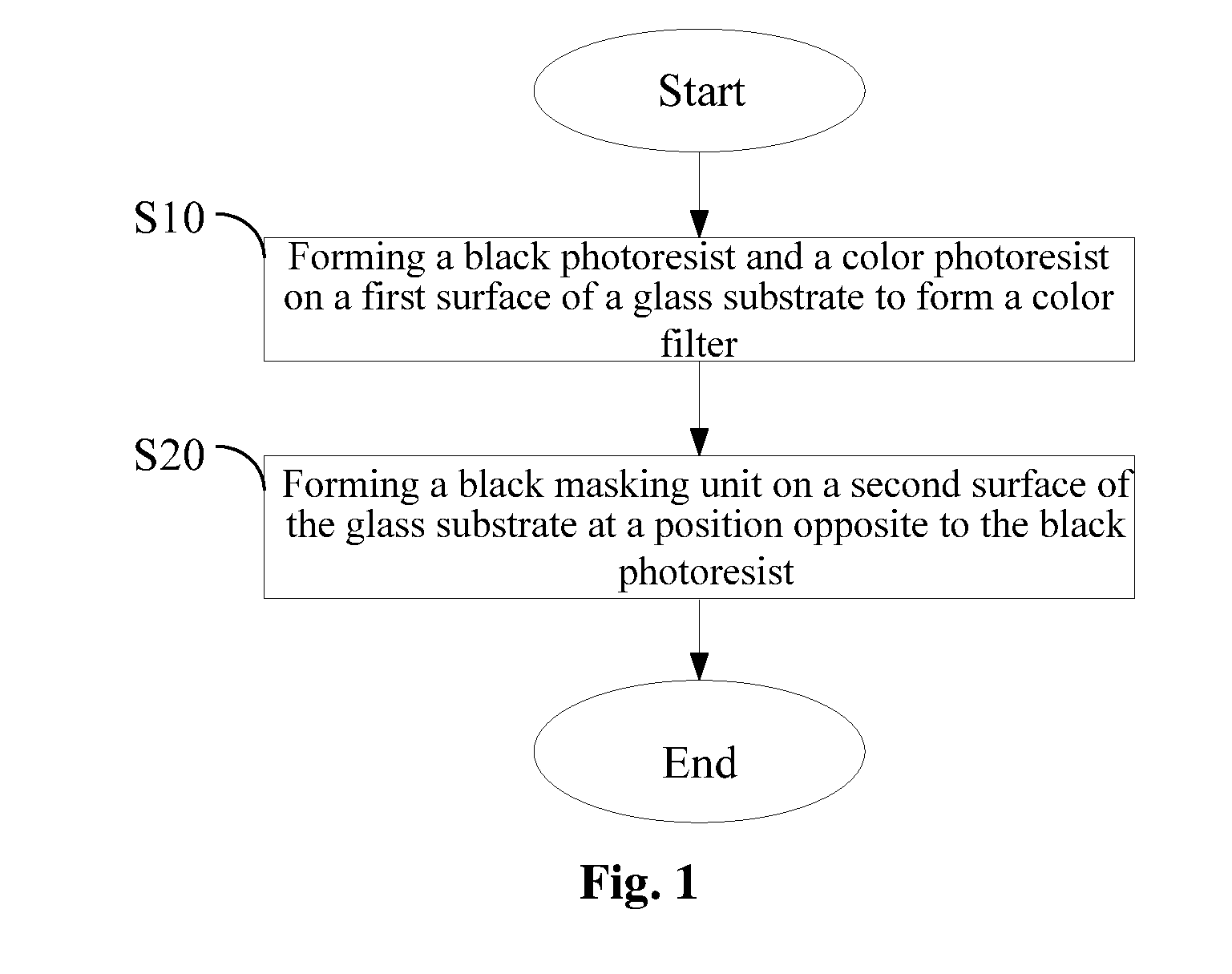
[0030]Referring to FIG. 1, there is shown a flowchart diagram of a preferred embodiment of a method for improving a view angle of an LCD according to the present invention.

[0031]In this embodiment, the method for improving a view angle of an LCD comprises the following steps.

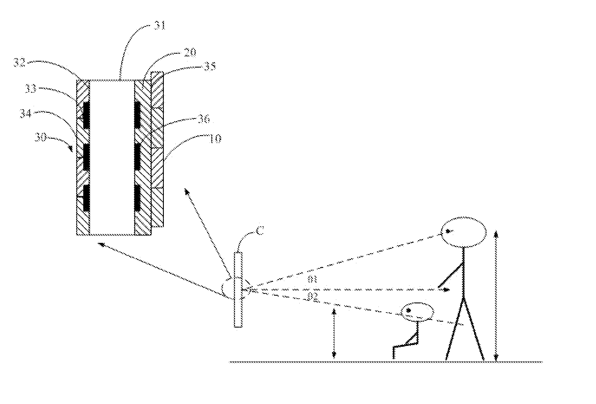
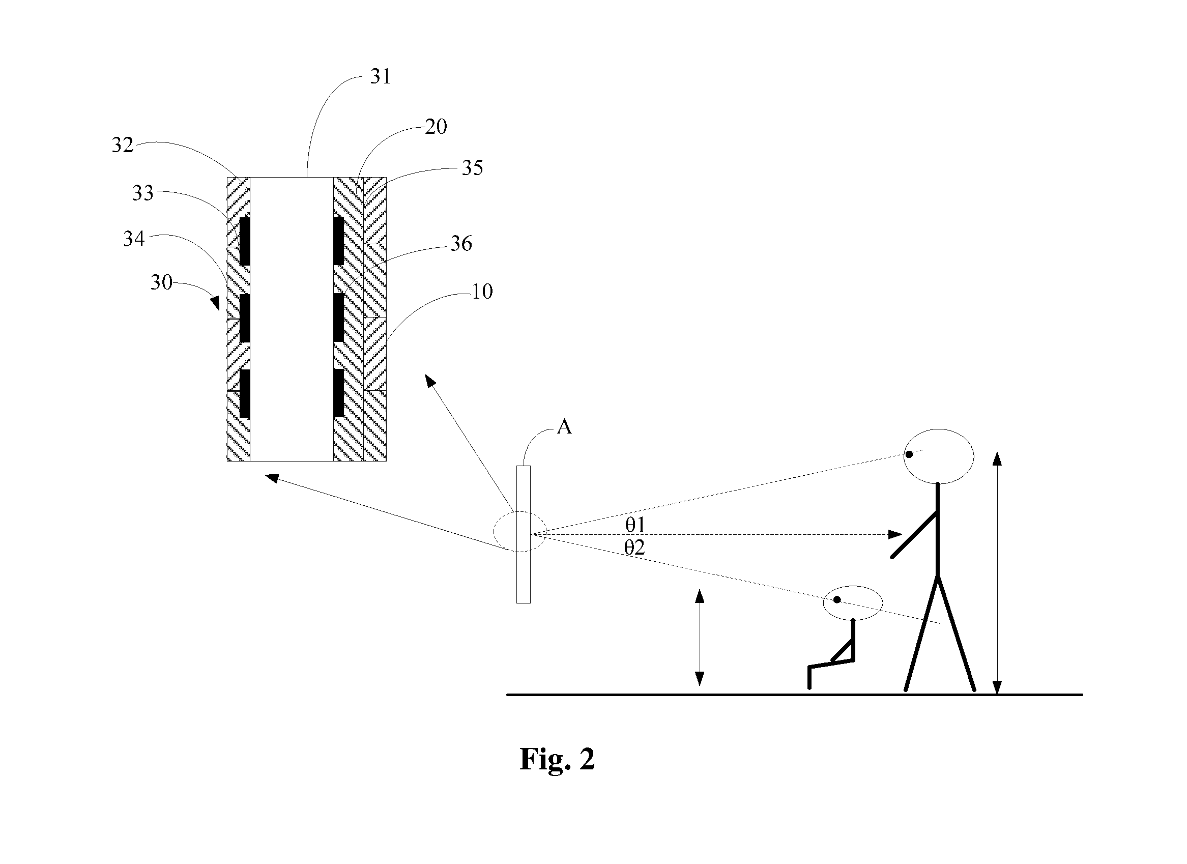
[0032]Step S10: forming a black photoresist and a color photoresist on a first surface of a glass substrate to form a color filter. In this embodiment, the LCD (i.e., a 3D phase retardation graphic LCD) comprises a color filter. The color filter is comprised of a glass substrate, a black photoresist and a color photoresist. The black photoresist and the color photoresist are coated on a surface of the glass substrate. For convenience of description, the surface coated with the black photoresist and the color photoresist is defined as a first surface, and a surface opposite to...


PUM

PropertyMeasurementUnit
included angleaaaaaaaaaa
total thicknessaaaaaaaaaa
widthaaaaaaaaaa

Abstract

A method for improving a view angle of a liquid crystal display (LCD) and the LCD are disclosed. The method comprises the following steps: forming a black masking unit on a second surface of the glass substrate at a position opposite to the black photoresist, the second surface and the first surface being opposite with each other, the black photoresist and the black masking unit being disposed at two sides of the glass substrate respectively. The method for improving a view angle of an LCD and the LCD of the present invention can improve the view angle of the LCD and increase the aperture ratio; additionally, the present invention can also enhance error tolerance in assembling the quarter-wave phase difference plate with the LCD, thus reducing the reject ratio.

Description

BACKGROUND[0001]1. Technical Field[0002]The present invention relates to the field of liquid crystal displaying, and more particularly, to a method for improving a view angle of a liquid crystal display (LCD) and the LCD.[0003]2. Description of Related Art[0004]As is well known, in a three-dimensional (3D) LCD, light from a polarizer at a color filter (CF) side of the LCD is linearly polarized light, which then propagates through a patterned half-wave phase difference plate and an isotropic material layer to become linearly polarized light rays perpendicular to each other. After propagating through quarter-wave phase difference plate both having an included angle of 45°, the two linearly polarized light rays become a left-hand circularly polarized light ray and a right-hand circularly polarized light ray respectively, which then propagate through quarter-wave phase difference plates of the eyeglasses to become linearly polarized light rays. The linearly polarized light rays then pro...

Claims


Application Information

Patent Timeline
Patent Type & Authority Applications(United States)
IPC IPC(8): G02F1/1333H01J9/00G02B30/30
CPCG02F1/133512G02F2001/133631G02B27/2214G02F2001/133638G02F1/133631G02F1/133638G02B30/30G02B30/27
Inventor HSIAO, CHIA-CHIANGCHEN, CHIH-WENHE, CHENGMING
Owner TCL CHINA STAR OPTOELECTRONICS TECH CO LTD
Why Eureka
Try Eureka