Polarization-Independent LCOS Device

a liquid crystal based, phase modulator technology, applied in the direction of phase-modulated carrier systems, digital transmission, instruments, etc., can solve the problems of device thickness, ineffective practice, and practical difficulties of optical devices, and achieve the effect of reducing the polarization sensitivity of phase control

Active Publication Date: 2013-03-21
II VI DELAWARE INC
View PDF2 Cites 33 Cited by
  • Summary
  • Abstract
  • Description
  • Claims
  • Application Information

AI Technical Summary

Benefits of technology

[0036]In accordance with a third aspect of the present disclosure, there is provided a method of substantially reducing p

Problems solved by technology

This technique presents practical difficulties in optical devices, particularly in ensuring the optical paths and trajectories of each separated polarization state are identical.
While the above described technique is relatively simple to implement, it is considerably inefficient in practice.
However, these elements still necessarily increase the device thickness, thereby increasing the required drive voltages.
Therefore, significant drive voltages may be required.
This technique is practically difficult to achieve using a typical CMOS platform.
Further, the presence of the addition

Method used


Image

  • Polarization-Independent LCOS Device
  • Polarization-Independent LCOS Device
  • Polarization-Independent LCOS Device

Examples


Embodiment Construction

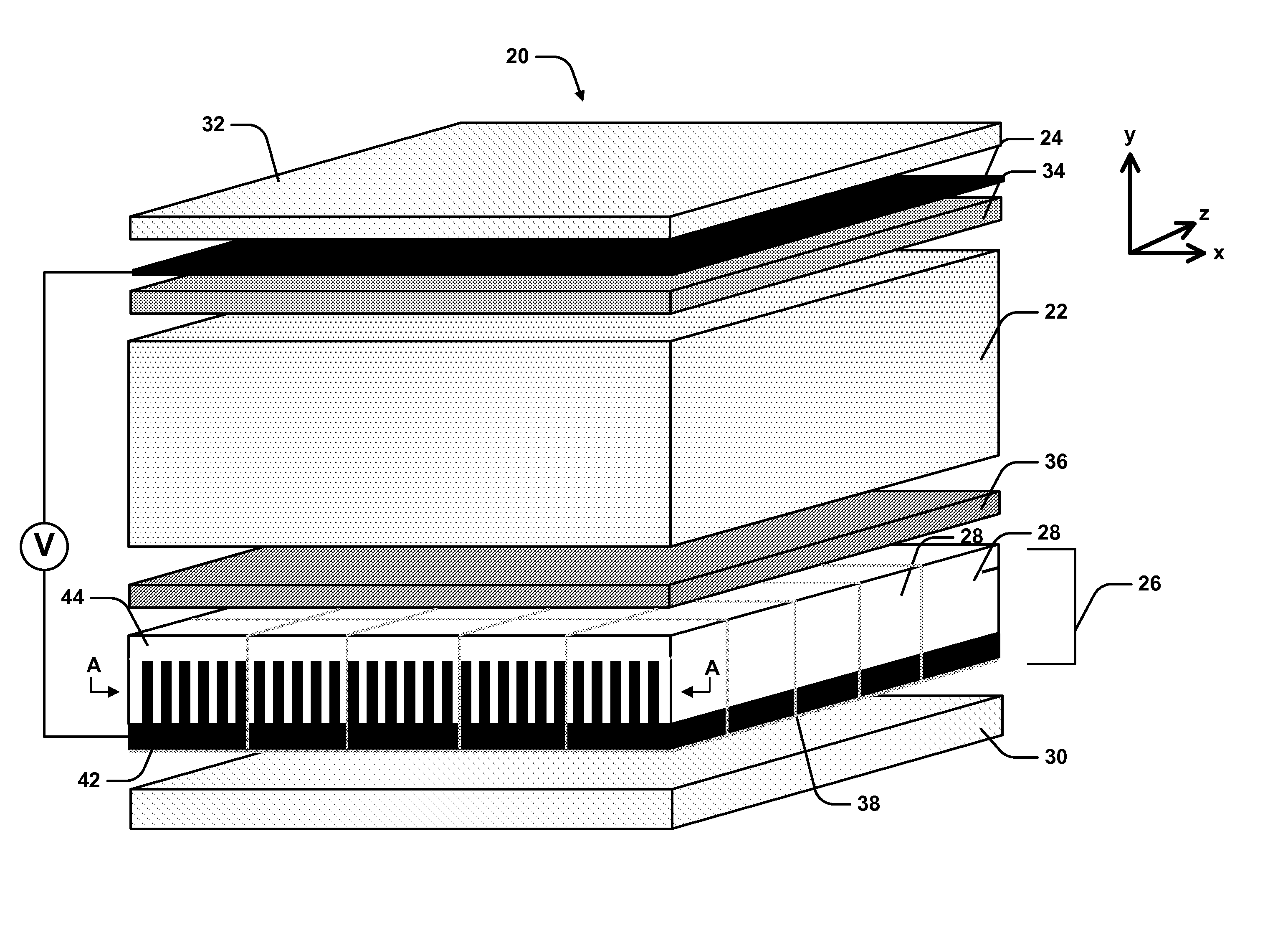
[0059]Referring initially to FIG. 5, there is illustrated schematically a cross-section of an optical phase modulator 20 including a liquid crystal element 22, disposed between a pair of opposing electrodes 24 and 26. The electrodes 24, 26 are electrically driven for supplying an electric potential V across the liquid crystal element 22 to drive the liquid crystals within element 22 in a predetermined configuration. Electrode 26 includes a grid of individually addressable pixels 28, each having a sub-wavelength grating structure that provides an anisotropic refractive index profile in orthogonal lateral dimensions, thereby creating an effective material form birefringence. Light incident through liquid crystal element 22 and onto electrode 26 is reflected and experiences a relative phase difference of 180° between its constituent orthogonal polarization components, thereby reflecting each polarization component in an orthogonal orientation.

[0060]During operation, each polarization c...


PUM


Abstract

Described herein is an optical phase modulator (20) including a liquid crystal element (22), disposed between a pair of opposing electrodes (24) and (26). The electrodes (24, 26) are electrically driven for supplying an electric potential V across the liquid crystal element (22) to drive the liquid crystals within element (22) in a predetermined configuration. Electrode (26) includes a grid of individually drivable pixel regions (28), at least some of which include a sub-wavelength grating structure that provides an anisotropic refractive index profile in orthogonal lateral dimensions, thereby creating an effective material form birefringence. Light incident through liquid crystal element (22) and onto electrode (26) is reflected and experiences a relative phase difference of 180° between its constituent orthogonal polarization components, thereby rotating each polarization component into the orthogonal orientation upon reflection.

Description

CROSS REFERENCE TO RELATED APPLICATIONS[0001]This patent application is a non-provisional of U.S. Provisional Patent Application Ser. No. 61 / 535,211 filed Sep. 15, 2011, entitled “Polarization-Independent LCOS Device.” The entire disclosure of U.S. Provisional Patent Application Ser. No. 61 / 535,211 is incorporated herein by reference.FIELD OF THE INVENTION[0002]The present invention relates to optical phase modulator devices and in particular to polarization independent liquid crystal based optical phase modulators. While some embodiments will be described herein with particular reference to that application, it will be appreciated that the invention is not limited to such a field of use, and is applicable in broader contexts.BACKGROUND[0003]Any discussion of the background art throughout the specification should in no way be considered as an admission that such art is widely known or forms part of common general knowledge in the field.[0004]Liquid crystal on silicon (LCOS) devices ...

Claims


Application Information

Patent Timeline
IPC IPC(8): H04L27/18
CPCH04L27/2096H04L27/18
Inventor FRISKEN, STEVEN JAMESBAXTER, GLENN WAYNEWU, QIHONG
Owner II VI DELAWARE INC
Why Eureka
Try Eureka