Variable optical retarder

a retarder and variable technology, applied in the field of optical retarders, can solve the problems of reducing the spatial uniformity of the applied electric field, requiring a polarized optical beam for proper operation, and reducing the effect of facilitating spatial uniformity of varied optical retardation of liquid crystal layer, and reducing optical loss and electric field fringing or shielding effects

Active Publication Date: 2018-04-17
LUMENTUM OPERATIONS LLC
View PDF30 Cites 1 Cited by
  • Summary
  • Abstract
  • Description
  • Claims
  • Application Information

AI Technical Summary

Benefits of technology

[0009]It is an objective of the invention to provide a variable optical retarder, in which the polarization sensitivity would be reduced without excessive optical loss or driving voltage penalties.
[0010]In accordance with the invention, a dielectric or semiconductor sub-wavelength grating is placed inside a liquid crystal variable optical retarder between an electrode and a liquid crystal layer. The sub-wavelength grating acts as a quarter-wave plate, while having a very small thickness, so that the driving voltage penalty due to the in-cell placement of the sub-wavelength grating is lessened. The sub-wavelength grating can also be made highly reflective, for example, it can include a multilayer dielectric high reflector, which further reduces optical loss in comparison with a metal reflector.
[0027](c) while performing steps (a) and (b), applying an electric field to the liquid crystal layer via a pair of flat electrodes external to, and parallel to the liquid crystal layer and the sub-wavelength grating, to vary an optical retardation of the liquid crystal layer, thereby varying the phase delay of the beam of light; wherein the flatness of the electrodes facilitates spatial uniformity of the applied electric field, thereby facilitating spatial uniformity of the varied optical retardation of the liquid crystal layer.
[0028]In a preferred embodiment, the sub-wavelength grating does not contain any metal, which reduces optical loss and electric field fringing or shielding effects.

Problems solved by technology

One disadvantage of liquid crystal variable retarders is that they typically require a polarized optical beam for proper operation.
This disadvantage, however, is not intrinsic and may be overcome by using an appropriate polarization diversity arrangement.
The increased beam spot size is detrimental in a variable retarder array configuration, in which the liquid crystal cell 12 is pixilated, because it reduces the spatial resolution.
Another disadvantage of the variable optical retarder 10 is that the liquid crystal cell 12 has to be transmissive to accommodate the external quarter-wave plate 11.
These requirements are somewhat contradictory, and as a result, the transparent electrodes usually introduce some extra optical loss into the system.
The resulting optical loss is lower in this case, because in the James device, the incoming optical beam passes twice through a single transparent electrode, not through two electrodes.
However, inside placement of the quarter-wave plate reduces electrical field across the liquid crystal layer, thus requiring a higher driving voltage to compensate for the electric field decrease.

Method used


Image

  • Variable optical retarder
  • Variable optical retarder
  • Variable optical retarder

Examples


Embodiment Construction

[0040]While the present teachings are described in conjunction with various embodiments and examples, it is not intended that the present teachings be limited to such embodiments. On the contrary, the present teachings encompass various alternatives, modifications and equivalents, as will be appreciated by those of skill in the art. In FIGS. 2A, 2B and 3A, 3B, and 3C, similar numerals refer to similar elements.

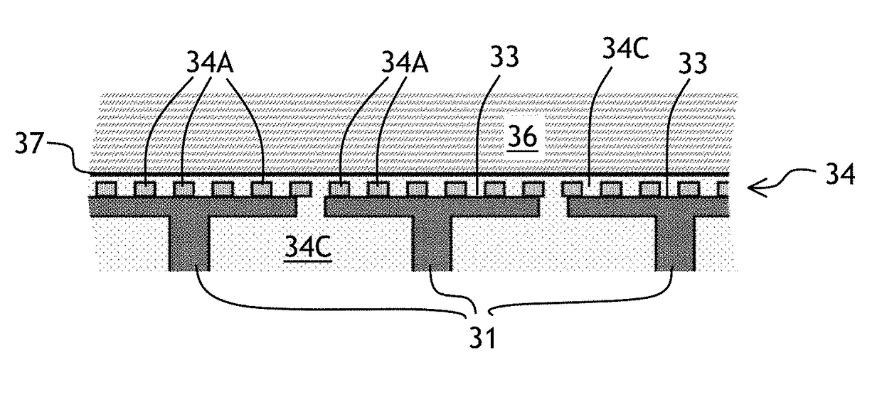
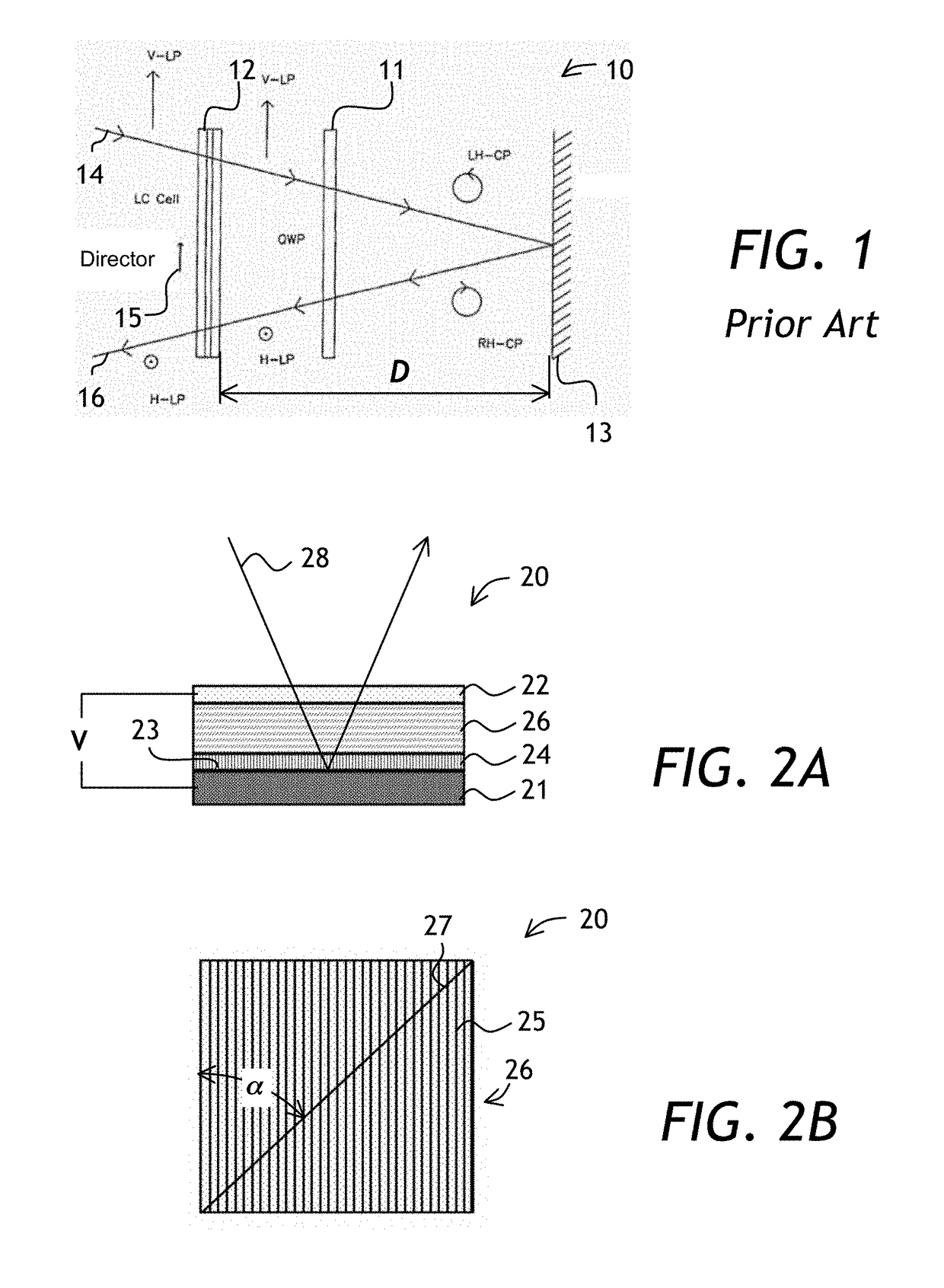
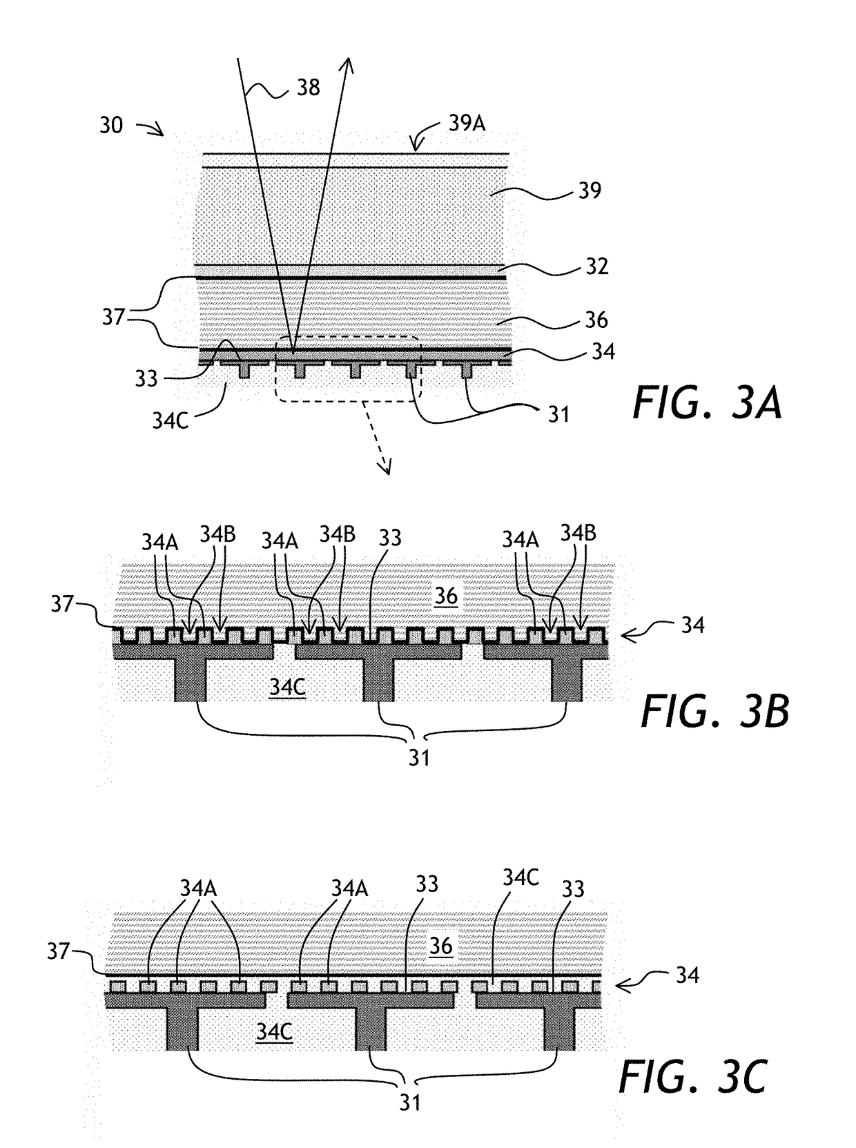
[0041]Referring to FIGS. 2A and 2B, a variable optical retarder 20 of the invention includes a first continuous flat electrode 21 and a second substantially transparent continuous flat electrode 22 opposed to the first electrode 21, a liquid crystal layer 26, and a sub-wavelength grating 24 disposed between the liquid crystal layer 26 and the first electrode 21. As seen in FIG. 2B, the sub-wavelength grating 24 has a plurality of grating lines 25 running parallel to each other. A director 27 of the liquid crystal layer 26 is at an angle α of 45 degrees with respect to the grat...


PUM

PropertyMeasurementUnit
acute angleaaaaaaaaaa
angleaaaaaaaaaa

Abstract

A sub-wavelength grating is placed inside a liquid crystal variable optical retarder to reduce polarization dependence of the optical retardation generated by the variable optical retarder. A small thickness of the sub-wavelength grating, as compared to a conventional waveplate, reduces the driving voltage penalty due to the in-cell placement of the sub-wavelength grating.

Description

CROSS-REFERENCE TO RELATED APPLICATIONS[0001]The present invention claims priority from U.S. Provisional Patent Application No. 61 / 692,896 filed Aug. 24, 2012, which is incorporated herein by reference.TECHNICAL FIELD[0002]The present invention relates to optical retarders, and in particular to variable optical retarders for imparting a variable phase delay to an optical beam.BACKGROUND OF THE INVENTION[0003]Liquid crystal variable optical retarders are used to impart a variable optical phase delay, and / or change the state of polarization of an optical beam. In a typical liquid crystal variable optical retarder, a few micrometers thick layer of a liquid crystal fluid is sandwiched between two transparent electrodes. When a voltage is applied to the electrodes, an electric field between the electrodes orients liquid crystal molecules, which are highly anisotropic. Field-induced orientation of the liquid crystal molecules changes an effective index of refraction of the liquid crystal ...

Claims


Application Information

Patent Timeline
Patent Type & Authority Patents(United States)
IPC IPC(8): G02F1/1335G02B5/32G02B5/30G02F1/153
CPCG02F1/1533G02B5/3083G02B5/32G02F1/133504G02F2201/307G02F1/1335
Inventor MILLER, JOHN MICHAELWILLS, GONZALO
Owner LUMENTUM OPERATIONS LLC
Why Eureka
Try Eureka