Reduction of polarization dependence in planar optical waveguides

a planar optical waveguide and polarization dependence technology, applied in the direction of optical waveguide light guide, instruments, optics, etc., can solve the problems of reducing the difference in the effective index of the waveguide mode for the two polarizations, and the birefringence of the waveguide giving rise to undesirable polarization dependence properties, so as to reduce the overlap of propagation, reduce the cte mis

Active Publication Date: 2005-09-08
LUMENTUM OPERATIONS LLC
View PDF5 Cites 2 Cited by
  • Summary
  • Abstract
  • Description
  • Claims
  • Application Information

AI Technical Summary

Benefits of technology

[0014] The present invention has found that polarization sensitivity can be reduced by reducing the CTE mismatch between the core and cladding, or by moving the birefringence away from the core / cladding boundary, or both. To accomplish this, silica material, or similar material for refractive index (RI) and CTE matching is applied between the core and cladding to waveguide features where significant transmission occurs in the cladding, such as high bend radius areas or close proximity coupling waveguides. The silica material USG (undoped silica glass) has a CTE substantially equal to the waveguide core and a RI substantially equal to the cladding material. The CTE match does not have to be exact, although it should be as close as possible, preferably within 0.2 ppm / K. This structure reduces overlap of propagating TE and TM modes with birefringence perturbation in the cladding.

Problems solved by technology

The waveguide birefringence may give rise to undesirable polarization dependence properties such as polarization dependent loss (PDL) and polarization dependent wavelength of the optical device.
Polarization dependence of waveguide devices originates from stress induced birefringence in the waveguide layers which perturbs the desired index profile of the waveguide and leads to a difference in the effective modal index for the two polarizations.
Stress birefringence can lead to a difference in the effective index of the waveguide modes for the two polarizations, which is particularly detrimental in phase sensitive devices such as an arrayed waveguide grating (AWG) or a Mach-Zehnder Interferometer (MZI).
For example, in an AWG, birefringence in the waveguides of the phase array leads to a splitting in the transmission spectrum of the device for the two polarizations, termed polarization dependent wavelength (PDW), resulting in an unacceptable polarization dependent loss if the PDW is large.
Polarization dependence in these devices is generally believed to be the result of differences of the thermal expansion properties between layers in the device structures causing stresses during the manufacturing process.
Asymmetric stress in the waveguide cores results in birefringence.
However, it has been found that the stress, and hence birefringence, in the cladding is the more dominant factor in limiting the polarization sensitivity of the device than the waveguide core birefringence.
It is known in the prior art to dope the cladding to match its CTE to that of the substrate for the purposes of reducing waveguide birefringence (A. Kilian, J. Kirchhof, B. Kuhlow, G. Przyrembel and W. Wischmann ‘Birefringence free planar optical waveguide made by FHD through tailoring of the overcladding’Journal of Lightwave Technology) but heavy doping affects the environmental stability of the device and the cladding to core stress is still present.
A further problem affecting the performance of planar waveguides is that during formation of the cladding and waveguiding layers gas pockets can be trapped under subsequent consolidated layers.
Such gas pockets disrupt the optical properties of the PLC layers.
Birefringence in the cladding layer is not recognized as a source of PDL, however, and because the CTE is not matched between the core and cladding interface, the cladding interface does not separate the refractive index from the birefringence.

Method used


Image

  • Reduction of polarization dependence in planar optical waveguides
  • Reduction of polarization dependence in planar optical waveguides
  • Reduction of polarization dependence in planar optical waveguides

Examples


Embodiment Construction

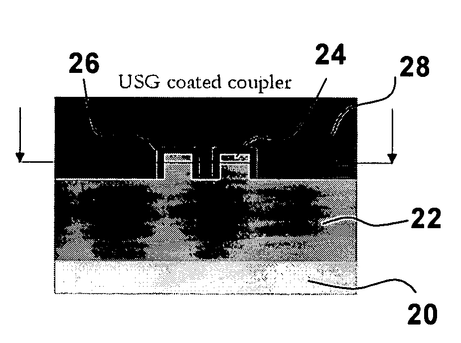
[0041] As discussed above, birefringence experienced in mode coupled devices is largely a result of thermal stress at the core / cladding interface caused by different coefficients of thermal expansion of the two materials during fabrication. Typically PLCs comprise a silicon substrate, cladding layers of borophosphosilicate glass (BPSG), and waveguide cores fashioned of germanosilicate glass (GSG) or phosphosilicate glass (PSG). The CTE of BPSG and GSG are approximately 3.4 ppm / K and approximately 1 ppm / K. Other materials used in PLCs, such as silicon oxynitride or aluminum oxide cause similar problems.

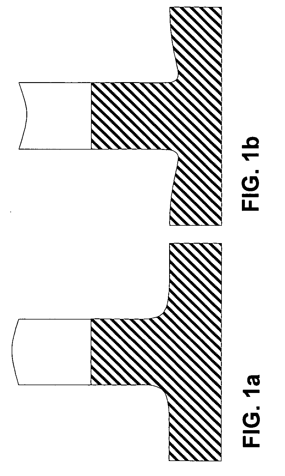
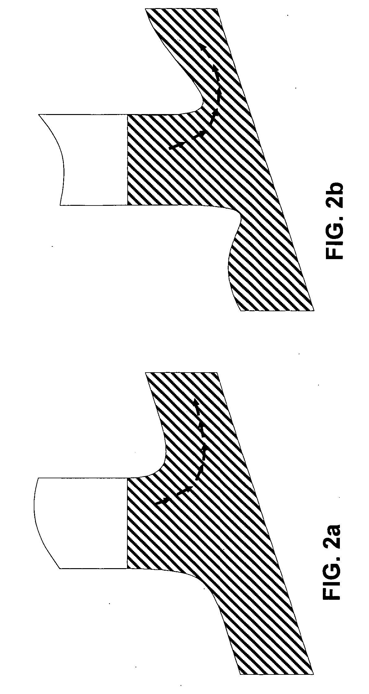
[0042] Stress induced birefringence in the cladding alters the cladding / core index profile of a waveguide differently for the TM and TE modes. As illustrated in FIG. 1a, the regular step function of an unstressed waveguide is raised and rounded for the TM mode permitting the TM light to pass through the core / cladding interface more easily. By contrast as seen in FIG. 1b, the refractiv...


PUM

PropertyMeasurementUnit
thicknessaaaaaaaaaa
refractive indexaaaaaaaaaa
lengthaaaaaaaaaa

Abstract

The invention relates to a method of reducing polarization dependence in planar optical waveguides using index and coefficient of thermal expansion (CTE) matched material between the optical waveguide core and the cladding layer. For coupled mode devices such as the directional coupler or mode conversion horn polarization sensitivity has been linked to birefringence in the cladding, since their operation is dependent on co-propagation of fundamental and higher order mode(s), which are not as strongly confined to the waveguide core. Polarization sensitivity can be reduced by reducing the CTE mismatch between the core and cladding, or by moving the birefringence away from the core/cladding boundary, or both. To accomplish this, silica material, or similar material for refractive index (RI) and CTE matching is applied between the core and cladding to waveguide features where significant transmission occurs in the cladding.

Description

CROSS-REFERENCE TO RELATED APPLICATIONS [0001] This application claims priority from U.S. provisional application No. 60 / 549,253 filed Mar. 2, 2004 which is incorporated herein by reference for all purposes.MICROFICHE APPENDIX [0002] Not Applicable. TECHNICAL FIELD [0003] The present application relates to a method of reducing polarization dependence in planar optical waveguides using index and coefficient of thermal expansion (CTE) matched material between the optical waveguide core and the cladding layer; and further relates to planar optical waveguide devices incorporating the same. BACKGROUND OF THE INVENTION [0004] Planar lightwave circuits (PLC) are optical devices including planar optical waveguides formed on a silicon wafer substrate, wherein the waveguides are made from transmissive media which have a higher refractive index than the outlying cladding layers in order to guide light along the optical path. PLCs are designed to integrate multiple components and functionalitie...

Claims


Application Information

Patent Timeline
Patent Type & Authority Applications(United States)
IPC IPC(8): G02B6/10G02B6/122G02B6/12G02F1/01G02F1/313
CPCG02F2202/40G02B6/126
Inventor HARWOOD, DUNCAN W.
Owner LUMENTUM OPERATIONS LLC
Why Eureka
Try Eureka