
Light distribution control member and illuminating device using the same

a technology of light distribution control and illuminating device, which is applied in the direction of lighting and heating apparatus, semiconductor devices for light sources, instruments, etc., can solve the problems of high production cost and difficult production, and achieve the effect of improving uniformity, easy and inexpensive production

Inactive Publication Date: 2013-03-21
MINEBEA CO LTD
View PDF17 Cites 34 Cited by
  • Summary
  • Abstract
  • Description
  • Claims
  • Application Information

AI Technical Summary

Benefits of technology

The present invention is aimed at providing a light distribution control member that can improve the uniformity of the illuminance on a surface, while remaining easy and affordable to produce. This invention can be used in an illuminating device. The technical effect of this invention is to improve the quality of lighting, making it more even and consistent across the area being illuminated.

Problems solved by technology

However, in circular cone prisms, the prism surface is generally constituted by a curved surface, and thus they are difficult to produce compared to multi-sided pyramid prisms whose prism surfaces are constituted by flat surfaces.
Thus, light distribution control members using circular cone prisms have a problem in that the production costs are high.

Method used


Image

  • Light distribution control member and illuminating device using the same
  • Light distribution control member and illuminating device using the same
  • Light distribution control member and illuminating device using the same

Examples


first embodiment

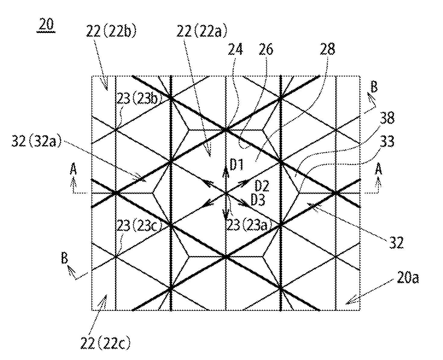
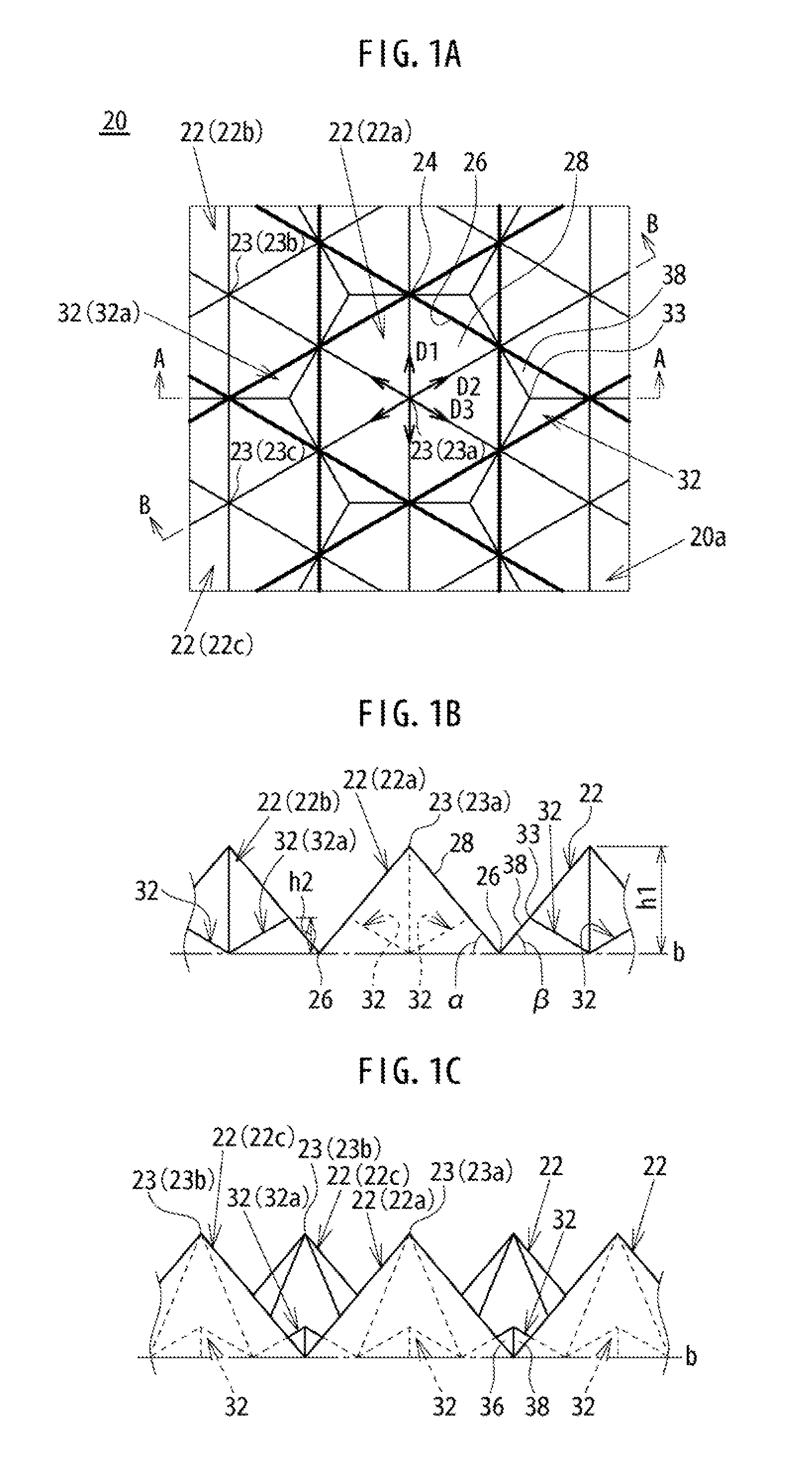
[0058]FIG. 1 illustrates a light distribution control member 20 according to the present invention. The light distribution control member 20 is made by molding a transparent resin material such as a methacrylic resin or a polycarbonate resin into a plate shape. The light distribution control member 20 is constituted so that one of the principal surfaces is a prism formation surface on which first prisms 22 and second prisms 32 to be explained below are provided. FIG. 1A is a plan view schematically illustrating a portion of a prism formation surface 20a of the light distribution control member 20. FIG. 1B is a cross-section view along line A-A in FIG. 1A, and FIG. 1C is a cross-section view along line B-B in FIG. 1A. In the light distribution control member 20, the principal surface (not illustrated) on the opposite side of the prism formation surface 20a can be constituted as a fiat surface.

[0059]The light distribution control member 20 includes a plurality of first prisms 22 havin...

second embodiment

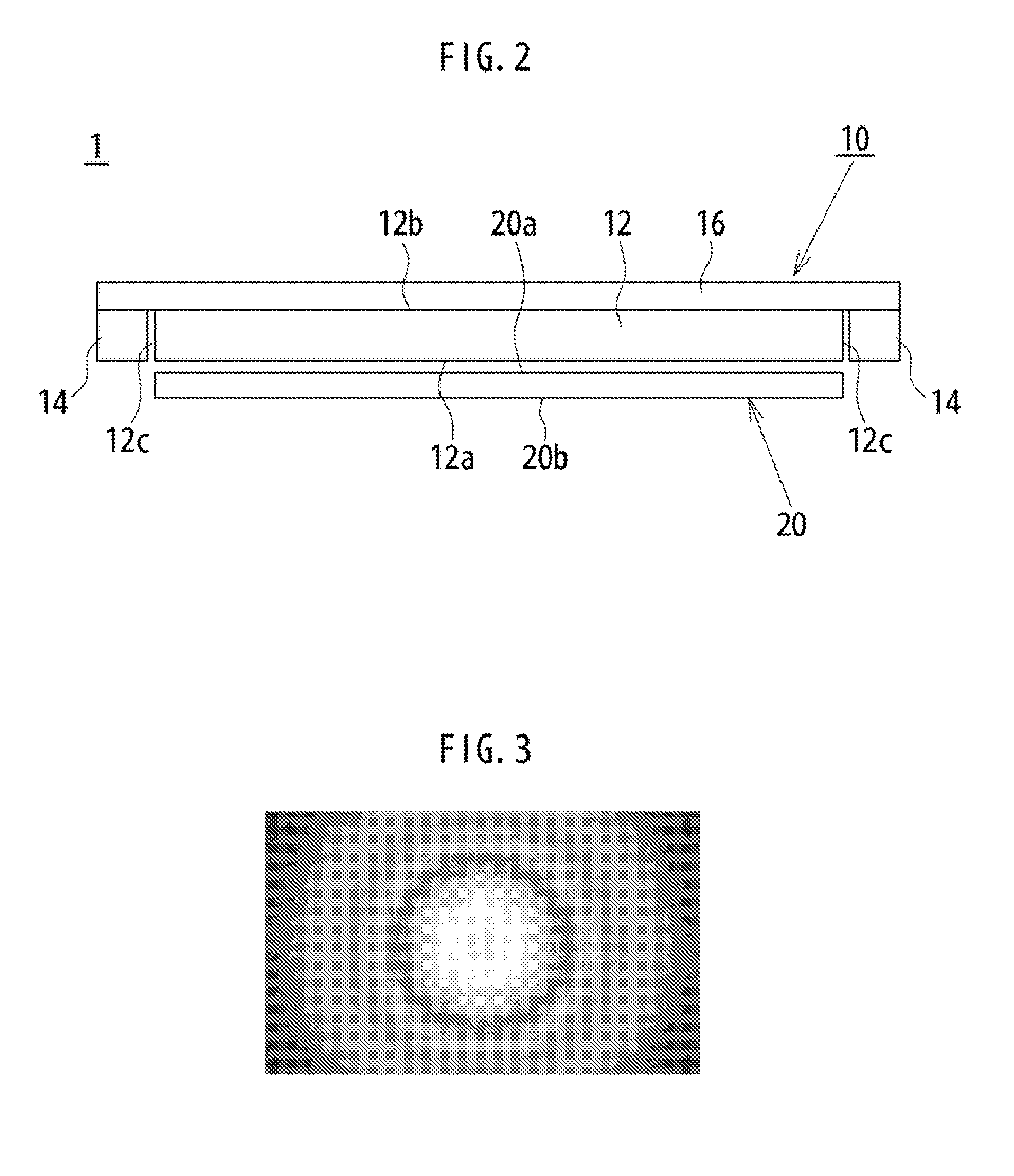
[0072]Next, an illuminating device including the light distribution control member 20 will be explained as the present invention. An illuminating device 1 shown in FIG. 2 includes a light source unit 10 including a light guide plate 12, light sources 14, and a reflective member 16. The light guide plate 12 is a plate-shaped light guide made by molding a transparent resin material such as a methacrylic resin or a polycarbonate resin. The light guide plate 12 is constituted so that one of the principal surfaces is an emitting surface 12a, and the emitting surface 12a is an emitting surface of the light source unit 10.

[0073]The light guide plate 12 has quadrilateral principal surfaces, and the side edge surfaces on the four sides are incident light surfaces 12c. The light sources 14 are arranged facing the incident light surfaces 12c. The light sources 14 include, for example, a plurality of light-emitting diodes arranged along the lengthwise direction (direction orthogonal to the pape...


PUM


Abstract

There is provided a light distribution control member with a plurality of first prisms that have inclined surfaces of which each edge of a hexagon is a base edge, and a plurality of second prisms that have inclined surfaces of which each edge of a triangle is a base edge. The first prisms are arranged in a houndstooth pattern, and the second prisms are arranged in areas surrounded by three first prisms.

Description

BACKGROUND OF THE INVENTION[0001]1. Field of the Invention[0002]The present invention relates to a light distribution control member capable of improving the uniformity of illuminance on a surface to be illuminated, and an illuminating device using the light distribution control member.[0003]2. Description of the Related Art[0004]An illuminating device generally has light distribution properties in which the luminous intensity is the greatest at the front face of the light emitting surface and the luminous intensity decreases as the angle from the front face increases. In an illuminating device with such light distribution properties, there has been a problem in that the illuminance on the surface to be illuminated (for example, the floor surface in the case that this kind of illuminating device is used by attaching it to a ceiling as indoor lighting), which is positioned at a distance from the illuminating device, is high only directly below the illuminating device, and rapidly dec...

Claims


Application Information

Patent Timeline
Patent Type & Authority Applications(United States)
IPC IPC(8): F21V5/02F21V8/00
CPCG02B5/0231G02B5/0278G02B5/045F21Y2105/00G02B6/0053F21Y2101/02F21V5/02F21Y2115/10
Inventor EDAMITSU, TAKASHIKATOH, SHUN
Owner MINEBEA CO LTD
Learn More