
Route control system and route control method in a switching apparatus

a control system and switching apparatus technology, applied in data switching networks, frequency-division multiplexes, instruments, etc., can solve the problem of needing professional knowledge for maintenance operation of every system

Inactive Publication Date: 2013-03-21
JUMIPER NETWORKS INC
View PDF4 Cites 2 Cited by
  • Summary
  • Abstract
  • Description
  • Claims
  • Application Information

AI Technical Summary

Benefits of technology

The present invention provides a route monitor control system and method that allows for efficient maintenance operation without the need for specialized knowledge. The system includes an OAM cell handler, virtual path handler, virtual channel handler, trunk, and control unit. The control unit sends an OAM cell send instruction to the specific OAM cell handler, carries out a loop back control to the virtual path handler, virtual channel handler, and trunk, and determines the fault position based on the returning or non-returning of the OAM cell from the object unit. The control unit may also carry out a switching operation of the route from the virtual path handler to the trunk for fault avoidance. The technical effect of the invention is to simplify the operation and maintenance of monitoring apparatuses and facilitate fault avoidance.

Problems solved by technology

However, because a managing method is different for every system in such a conventional route monitor control system, there is a problem to need professional knowledge for maintenance operation for every system.

Method used


Image

  • Route control system and route control method in a switching apparatus
  • Route control system and route control method in a switching apparatus

Examples


Embodiment Construction

[0022]Hereinafter, a route monitor control system in an ATM switching apparatus of the present invention will be described below with reference to the attached drawings.

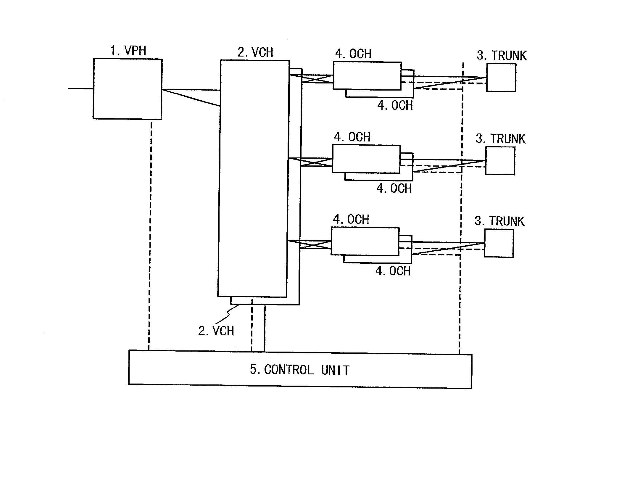
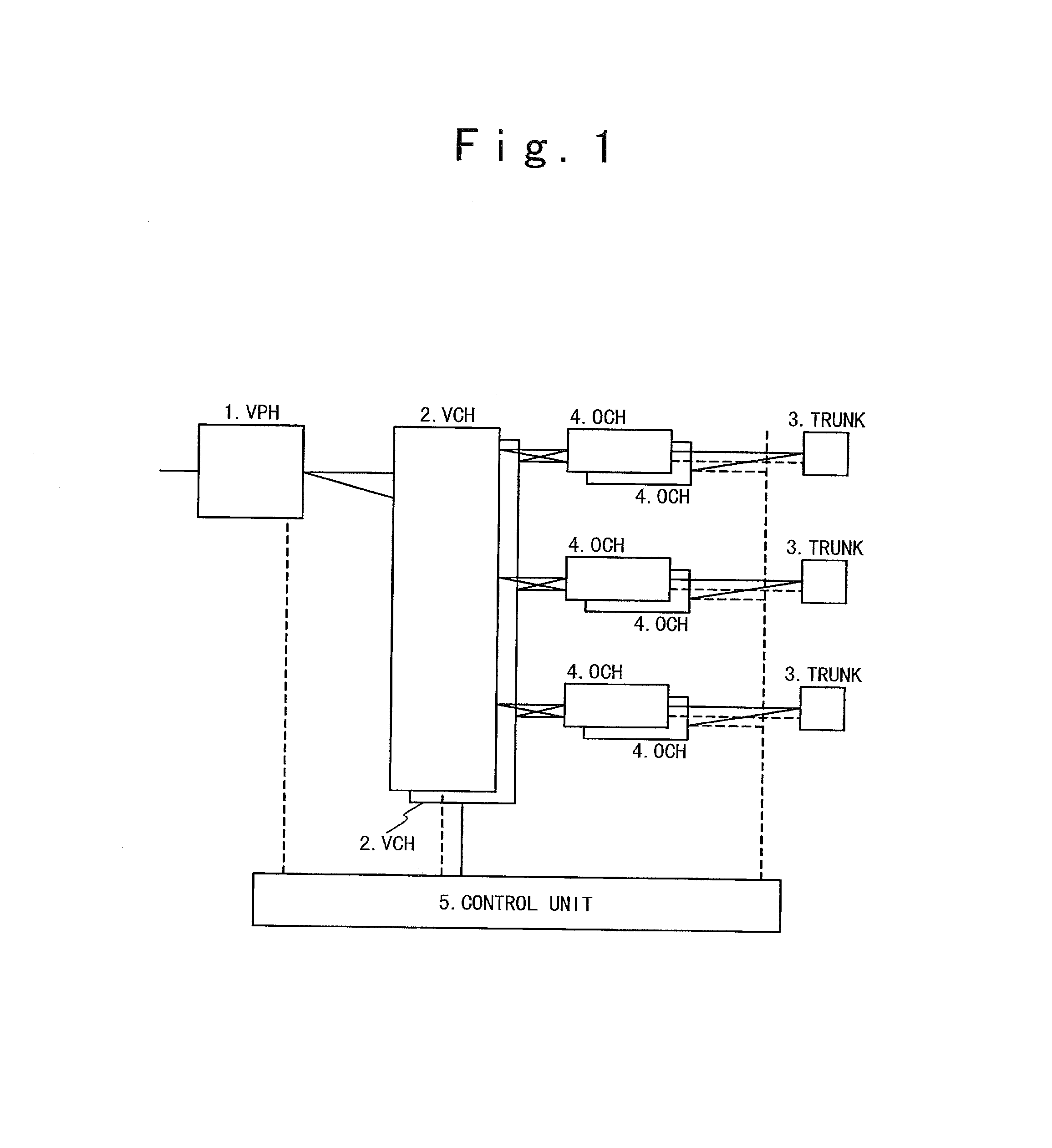
[0023]FIG. 1 is a block diagram showing the structure of the route monitor control system according to an embodiment of the present invention. As shown in FIG. 1, the route monitor control system in the embodiment is composed of a plurality of virtual path handler (VPHs) 1, a plurality of virtual channel handlers (VCHs) 2, a plurality of trunks 3, a plurality of OAM cell handlers (OCHs) 4 and a control unit 5. Also, the virtual path handlers (VPHs) 1, the virtual channel handlers (VCHs) 2, the trunks 3, the OAM cell handlers (OCHs) 4 and the control unit 5 are provided in an ATM switching apparatus.

[0024]The virtual path handler (VPH) 1 relays a virtual path (VP). The virtual channel handler (VCH) 2 relays a virtual channel (VC). The trunk 3 is a unit for the termination of the VC. The OAM cell handler (OCH) 4 proces...


PUM


Abstract

A system includes a cell handler, a virtual path handler, a virtual channel handler, a trunk. and a controller. The controller initiates, based on issuing an instruction to the cell handler, a loop-back control test. The loop-back control test involving transmission of an operation and maintenance (OAM) cell from the cell handler, via the virtual path handler, the virtual channel handler, and the trunk, and back to the cell handler. The controller further monitors the OAM cell, detects a fault based on monitoring the OAM cell; and perform fault avoidance based on detecting the fault.

Description

BACKGROUND OF THE INVENTION[0001]1. Field of the Invention[0002]The present invention relates to a route monitor control system which monitors an ATM (Asynchronous Transfer Mode) switching apparatus, and a route monitor control method.[0003]2. Description of the Related Art[0004]In recent years, a variety of services supported by an ATM switching apparatus are required in rapid spreading of a market of the ATM switching apparatus. Therefore, various types of hardware is installed into the ATM switching apparatus to provide the variety of services and a service function of each type of hardware is extended.[0005]On the other hand, in the quality verification of these hardware functions, after a maintenance person recognizes a kind of hardware to be verified, a maintenance command is given to carry out a conductiveness test between a trunk and a node by a monitoring apparatus installed in or out of the system.[0006]However, because a managing method is different for every system in su...

Claims


Application Information

Patent Timeline
Patent Type & Authority Applications(United States)
IPC IPC(8): H04L12/24H04L69/40H04M3/24H04M3/26H04Q11/04
CPCH04L2012/562H04Q11/0478H04L2012/5625
Inventor TAKASAKI, YOSHINORI
Owner JUMIPER NETWORKS INC
Learn More