Communications apparatus transmitting data on channels adaptively switchable

a communication apparatus and channel technology, applied in the field of communication apparatus, can solve the problems of not a little increase in overhead, and achieve the effects of reducing possible overhead due to channel reservation, reducing radio interference, and improving throughpu

Active Publication Date: 2013-03-21
OKI ELECTRIC IND CO LTD
View PDF4 Cites 8 Cited by
  • Summary
  • Abstract
  • Description
  • Claims
  • Application Information

AI Technical Summary

Benefits of technology

[0014]By employing the above configurations, the present invention have advantages that, without premising on temporal synchronization, the radio interference can be reduced and the throughput is improved, whereby possible overhead due to channel reservations can be reduced and efficient communication over a plurality of channels can be implemented.

Problems solved by technology

That raises a problem that increasing overhead is not a little in comparison to a case where only data is directly transmitted without running the reservation sequence.

Method used


Image

  • Communications apparatus transmitting data on channels adaptively switchable
  • Communications apparatus transmitting data on channels adaptively switchable
  • Communications apparatus transmitting data on channels adaptively switchable

Examples


first embodiment

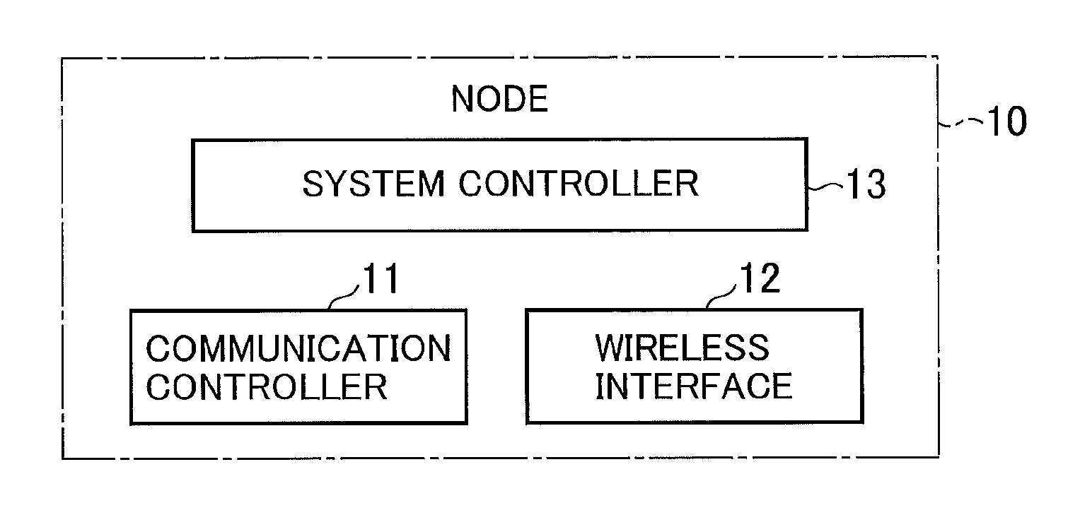
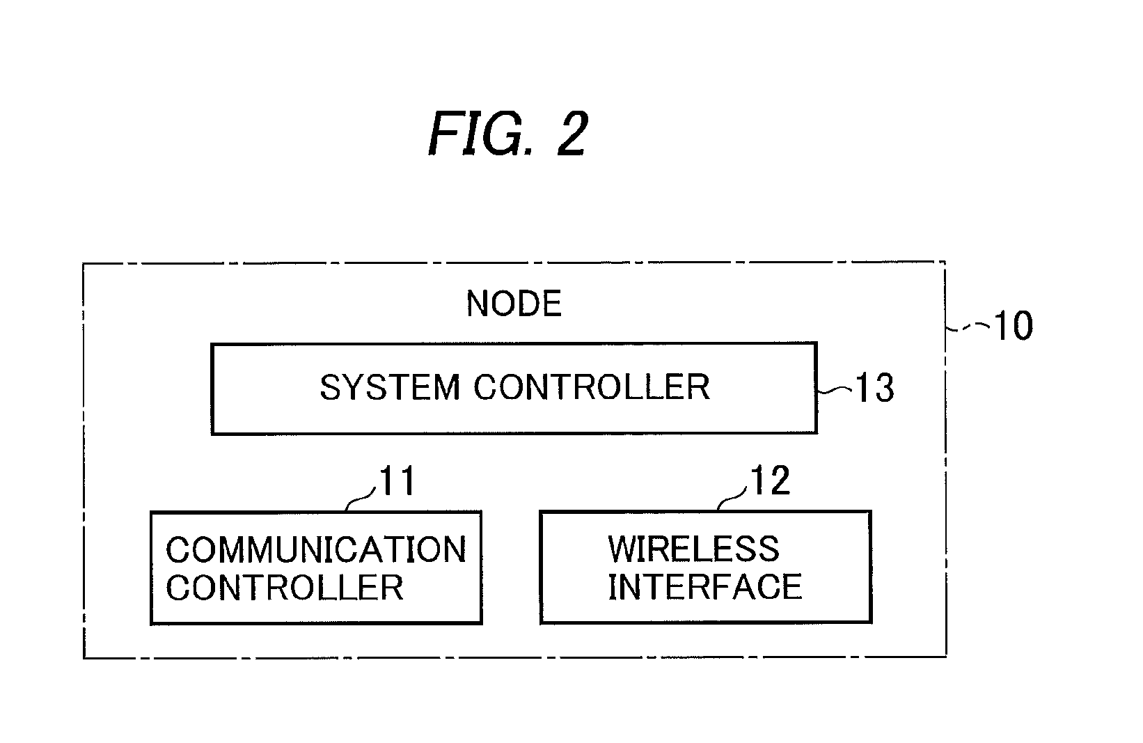
[0094]The alternative embodiment may basically be applied to the node structure 10 shown in and described with reference to FIG. 2. The alternative embodiment may be the same as the first embodiment except for the way of routing over a network by means of a tree routing protocol, and the functions of the communication controller 11 of the nodes 10.

[0095]The alternative embodiment is further different in that a reference node, or “root”, in a network tree has a plurality of wireless interfaces. The root may be any node that can be a standard. For instance, the root may be one residing on the top of the network tree, or one lying somewhere on the downstream from the top of the network tree when organized into a hierarchical structure.

[0096]FIG. 8 is a schematic block diagram showing the functional structure of a communication controller 20 of the node 10 in the instant alternative embodiment. In the figure, the communication controller 20 may comprise a channel determiner 6 in additio...

third embodiment

[0137]Now, the operation of communication proceeding will be described by referring further to FIG. 13 of the drawings. It is assumed merely for description that initially the same channel numbers of channels A and channel B are respectively set to “ch1” and “ch2” throughout all nodes 10 in the network 61.

[0138]Each node 10 sends out a routing control packet to establish a network connection. It is to be noted that the type of algorithm for use in routing may not be limitative, but various types of algorithm can be used. For example, AODV, OLSR and DSR algorithms may be applied. Once the routing is completed and the network connection is built, each node 10 can transmit data packets.

[0139]FIG. 13 is a flowchart of the operation of packet transmission carried out in the nodes 10. When the transmission controller 3 is supplied with a packet 55 to be sent, the packet type determiner 9 makes a determination on whether the packet is of an uplink or downlink frame (step S401). If the pac...


PUM


Abstract

In a communications apparatus, a communication controller transmits and receives signals on any of plural channels. A channel switching controller is responsive to channel switching information selectively defining plural reception-waiting periods using the channels to alter a channel to be used by the communication controller. A neighboring node channel controller exchanges channel switching information with other nodes to manage the channel switching information received from the other nodes. When transmitting transmission signals, a transmission controller refers to the channel switching information of the other nodes, and controls repetitive transmission of the transmission signals on the channel thus searched for.

Description

BACKGROUND OF THE INVENTION[0001]1. Field of the Invention[0002]The present invention relates to a communications apparatus, and more specifically to a communications apparatus applicable to a telecommunications network, such as a sensor network, formed by plural communications node devices spatially distributed to perform wireless data communication therebetween.[0003]2. Description of the Background Art[0004]In recent years, a type of wireless network is demanded in which plural communications channels, or multi-channels, are available to wireless terminals to carry out multiple, simultaneous communications over the different channels.[0005]IEEE (Institute of Electrical and Electronics Engineers) 802.11 DCF (Distributed Coordination Function), an existing standardized system widely applied as a conventional channel access solution in wireless networks, uses a single wireless channel to be shared between neighbor terminals, which may access the channel at random to conduct data com...

Claims


Application Information

Patent Timeline
Patent Type & Authority Applications(United States)
IPC IPC(8): H04W84/18
CPCH04W84/18H04L1/1867H04W72/1257H04W72/0446H04W28/06H04W72/535
Inventor KUBO, YUKINOZAKI, MASANORIYANAGIHARA, KENTAROUNISHIMURA, HIROSHI
Owner OKI ELECTRIC IND CO LTD
Why Eureka
Try Eureka