
Determining the specific orientation of an object

a specific orientation and object technology, applied in the field of determining the specific orientation of objects, can solve the problem that the marker does not necessarily give straight forward information about the actual positioning of the object to the user, and achieve the effect of facilitating the user's understanding of the actual spatial situation and estimating the necessary movement steps

Active Publication Date: 2013-03-21
KONINKLIJKE PHILIPS ELECTRONICS NV
View PDF10 Cites 9 Cited by
  • Summary
  • Abstract
  • Description
  • Claims
  • Application Information

AI Technical Summary

Benefits of technology

The present invention provides a technology that enhances the ability of users to position objects. The technology provides direct, straightforward information without requiring any interpretation or imaginative steps on the user's part. This allows users to focus on their tasks without being distracted by other steps. The technology also provides spatial information about the position and rotation of objects in relation to the user's chosen target or index position. This helps users to easily estimate the necessary movement steps to achieve the desired position. Overall, this technology helps users to better understand the actual spatial situation with respect to their chosen object.

Problems solved by technology

As a further disadvantage, the markers do not necessarily give straight forward information about the actual positioning of the object to the user.

Method used


Image

  • Determining the specific orientation of an object
  • Determining the specific orientation of an object
  • Determining the specific orientation of an object

Examples


Embodiment Construction

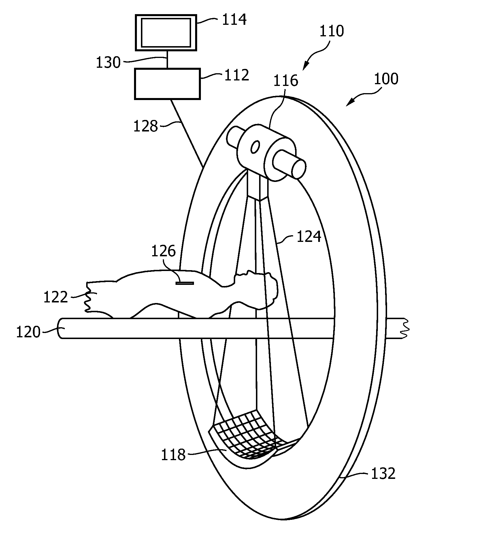
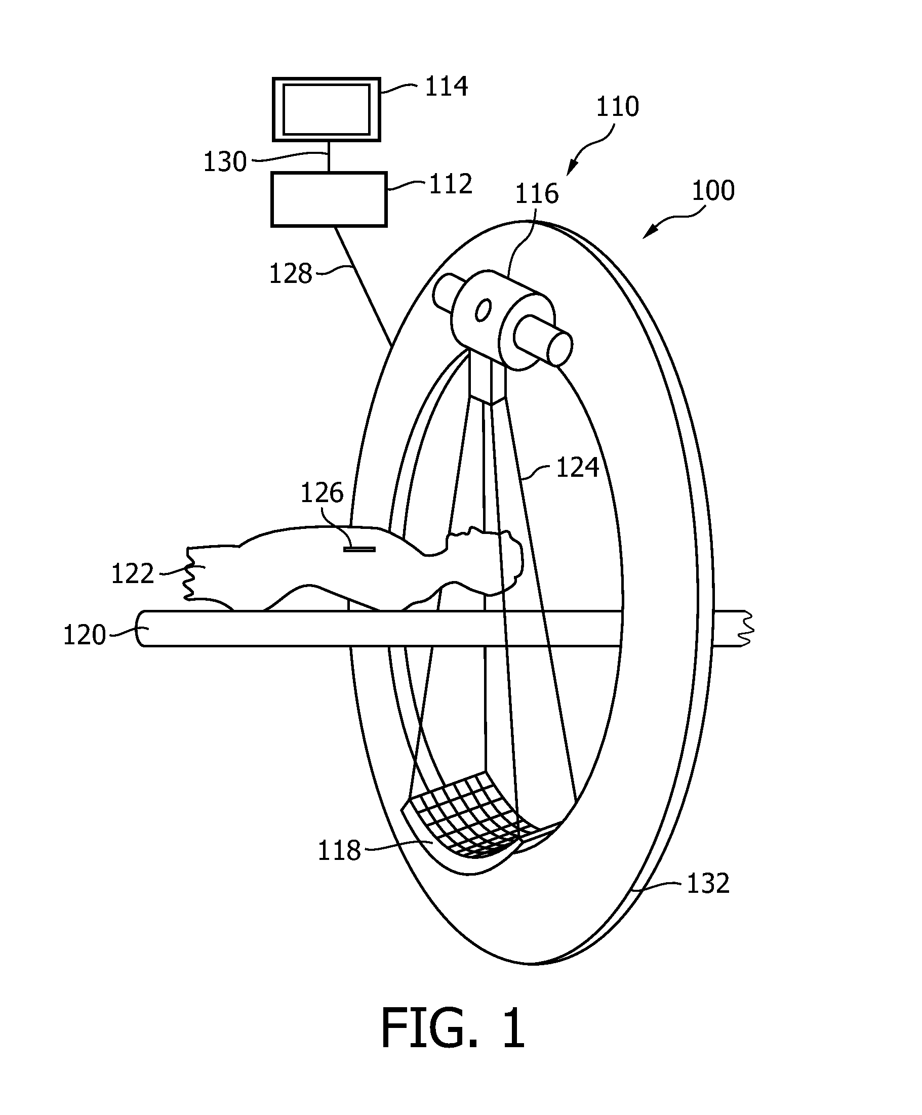
[0031]In FIG. 1, a medical imaging system 100 is shown, the system comprising image acquisition means 110, a data processing unit 112, and a display 114. The acquisition means 110 comprise an X-ray source 116 and a detector arrangement 118. Further, a table 120 is provided on which an object of interest, for example a patient 122, can be arranged. For the acquisition by the acquisition means 110, the patient 122 on the table 120 can be arranged between the X-ray source 116 and the detector arrangement 118 such that X-rays 124 radiating from the X-ray source towards the detector arrangement 118 pass a region of interest of the patient 122.

[0032]Further, an object 126 is shown provided with at least three markers visible in a 2D image acquired by the acquisition means 110. It must be noted that the markers are not shown in FIG. 1. The acquisition means 110 are adapted to acquire 2D image data of an object, for example the object 126 with three markers. In the exemplary embodiment show...


PUM


Abstract

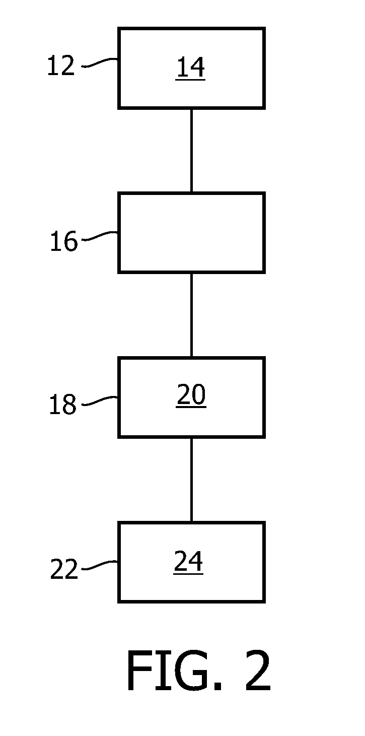
The present invention relates to the determination of the specific orientation of an object. In order to provide enhanced positioning information of an object to a user, a medical imaging system and a method for operating of a medical imaging system are proposed wherein 2D image data (14) of an object is acquired (12) with an imaging system, wherein the object is provided with at least three markers visible in the 2D image; and wherein (16) the markers are detected in the 2D image; and wherein the spatial positioning and rotation angle (20) of the object in relation to the system geometry is identified (18) on behalf of the markers; and wherein an object-indicator (24) is displayed (22) indicating the spatial positioning and rotation angle of the object.

Description

FIELD OF THE INVENTION[0001]The present invention relates to the determination of the specific orientation of an object. In particular, the present invention relates to a medical imaging system and a method for operating of a medical imaging system as well as computer program element for controlling a medical imaging system and to computer readable medium having stored such a computer program element.BACKGROUND OF THE INVENTION[0002]For determining the position of an object located in a region of interest, medical imaging systems provide two-dimensional image data to a user. From WO 2006 / 114721 A2, a method is known wherein a tool is provided with markers which are visible in the images acquired by an imaging system. From the marker location information in the images, the tool location information can be derived. But two markers do not provide any rotational information.SUMMARY OF THE INVENTION[0003]As a further disadvantage, the markers do not necessarily give straight forward info...

Claims


Application Information

Patent Timeline
IPC IPC(8): G06T7/00
CPCA61B6/12G06T7/0012A61B8/0833A61B8/0841A61B8/4416A61B19/5225A61B19/54A61B2019/524A61B2019/5242A61B2019/5425A61B2019/5454A61B2019/5466A61B2019/5495A61F2/2418A61F2/82A61F2250/0098G06T7/0042G06T2207/10088G06T2207/10116G06T2207/10132G06T2207/30052G06T2207/30101G06T2207/30204A61B6/5247A61B2090/3764A61B2090/3995A61B90/37A61B2090/3762A61B90/39A61B2090/3925A61B2090/3954A61B2090/3966G06T7/73
Inventor WAECHTER-STEHLE, IRINAKNESER, REINHARDLEHMANN, HELKOWEESE, JURGEN
Owner KONINKLIJKE PHILIPS ELECTRONICS NV
Learn More