
Spacer and Associated Method for Laying Tile

a spacer and associated technology, applied in the field of tiles and slabs, can solve the problems of unattractive and undesirable tile surface, unfavorable tile surface, and inability to properly align adjacent tiles along a working surface during installation, and achieve the effect of facilitating additional alignment and leveling of tiles

Inactive Publication Date: 2013-03-28
MIYAMOTO SCOTT
View PDF3 Cites 18 Cited by
  • Summary
  • Abstract
  • Description
  • Claims
  • Application Information

AI Technical Summary

Benefits of technology

The present invention provides a spacer for laying tile which can be used to create a space between tiles and a working surface to receive a substrate layer. The spacer has a base plate with a thickness that matches the thickness of the substrate layer, and can be secured to the working surface using an adhesive layer or a through bore with a recess. The base plate has a plurality of fins that are sized and configured to create space between the tiles for a mortar joint. The method involves positioning the tiles against the base plates of the spacers and inserting a measure of substrate material in the spaces between the tiles to form a mortar joint, which is then allowed to set to create a finished tile surface. The technical effects of the invention are that it provides a precise and easy way to establish the spacing and alignment of tiles, and a repositionable spacer that allows for additional alignment and leveling of the tiles.

Problems solved by technology

Proper alignment of adjacent tiles along a working surface during installation is often a time-consuming and labor-intensive process, but is nonetheless important for a number of reasons.
For example, if one tile in an array of tiles forming a tile surface is misaligned in a direction along the working surface, the width of the mortar joints between the misaligned tile and adjacent tiles is often not uniform, the end result often being an unattractive and undesirable tile surface.
If one tile in an array of tiles forming a surface is misaligned in a direction normal to the working surface, the end result is often an unacceptably non-planar tile surface.
The operation of laying, aligning, and leveling tiles is often difficult due, in part, to uneven working surfaces underlying the tile, such as for example, bowed or sagging floor surfaces.
In such cases, it is often difficult to establish a co-planar relationship of the top surfaces of the tiles, in part due to the tendency of the substrate layer (and subsequently, the tiles overlaid thereon) to follow the contour established in the initial surface.
Furthermore, it is not uncommon for tiles to shift or sink into the substrate layer as the adhesive sets.
In the event a tile becomes misaligned during setting of the adhesive, it is often difficult to realign the tile without disturbing adjacent tiles.
Use of the device of the '856 patent is itself a difficult task in that the grid is heavy and requires repeated moving and positioning adjustments as the tile installation operation progresses.
Moreover, such tile racks are expensive, and their use is time consuming, requiring different sizes and patterning according to the tiles being laid.

Method used


Image

  • Spacer and Associated Method for Laying Tile
  • Spacer and Associated Method for Laying Tile
  • Spacer and Associated Method for Laying Tile

Examples


Embodiment Construction

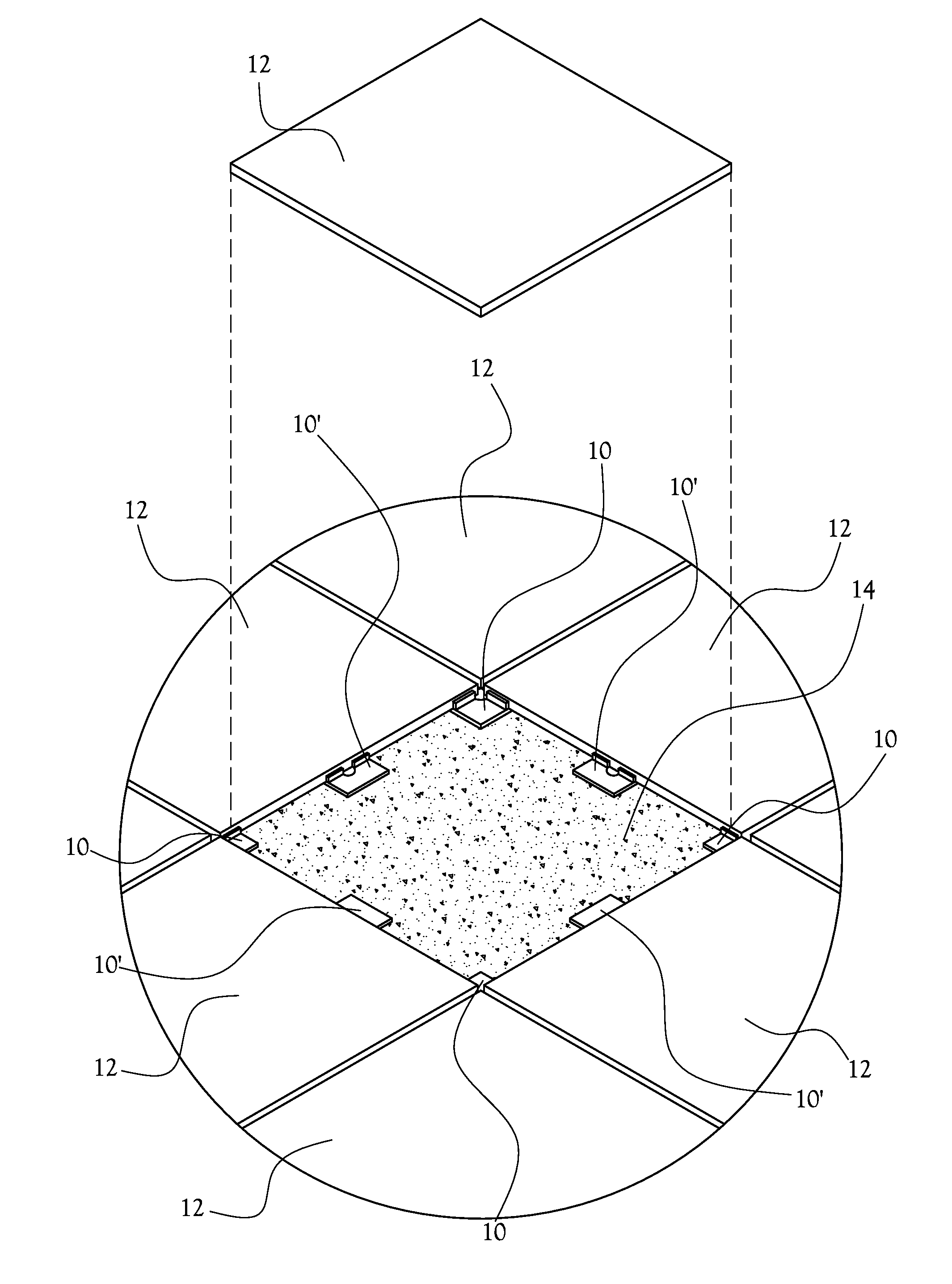
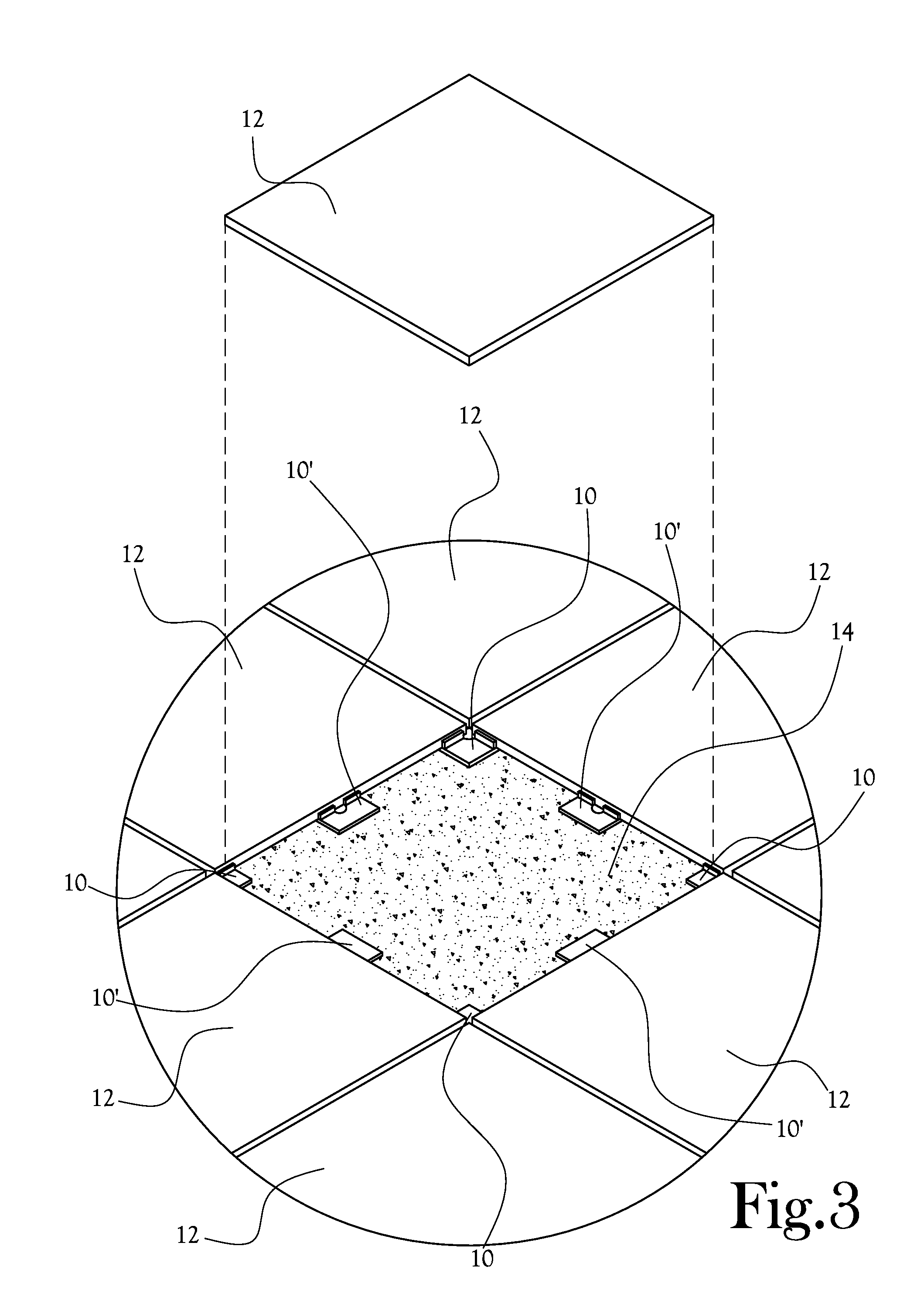
[0022]A spacer for laying tile 10 is disclosed herein and in the various figures. The spacer for laying tile, or spacer 10, is adapted to be interposed between adjacent tiles 12 of a plurality of tiles 12 and between the plurality of tiles 12 and a working surface 14 over which the tiles 12 are laid to assist in aligning and leveling the plurality of tiles 12 relative to each other and relative to the working surface 14. In several embodiments, the spacer 10 is helpful in promoting a co-planar arrangement of spaced apart tiles 12 such that a space is provided between each tile 12 and the working surface 14 sufficient to accommodate a substrate layer 26 of a desired thickness between each tile 12 and the working surface 14, and such that even spaces are provided between adjacent tiles 12 for receipt of mortar joints 16 therein.

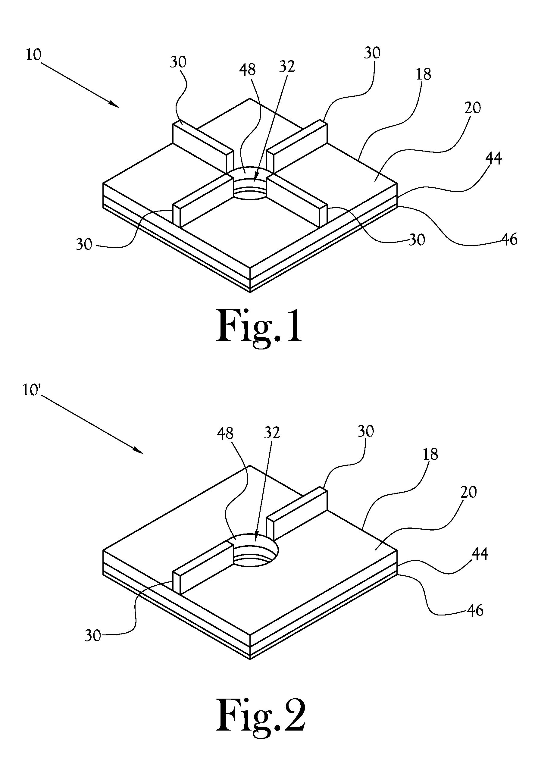
[0023]With initial reference to FIGS. 1 and 4, one embodiment of the spacer 10 includes a planar base plate 18 which is dimensioned to extend along a working s...


PUM


Abstract

A spacer for laying tile, which is useful for example in establishing a desired spacing and alignment between at least two adjacent tiles and between the tiles and a working surface, is disclosed. A substantially planar base plate is provided which is sized to extend between the working surface and an interface of adjacent sides of at least two adjacent tiles to establish a space between the tiles and the working surface for receipt of a substrate layer therein. A plurality of fins extend from a first surface of the base plate. Each fin is sized and configured along the base plate to extend between and abut adjacent sides of at least two adjacent tiles to establish a space between the tiles for receipt of a mortar joint therebetween.

Description

CROSS-REFERENCE TO RELATED APPLICATIONS[0001]Not ApplicableSTATEMENT REGARDING FEDERALLY-SPONSORED RESEARCH OR DEVELOPMENT[0002]Not ApplicableBACKGROUND OF THE INVENTION[0003]1. Field of Invention[0004]The present general inventive concept relates to tiles, slabs, or the like (hereinafter “tiles”). More particularly, the present general inventive concept pertains to a spacer for aligning and leveling adjacent tiles to assist in laying the tiles onto floors, walls, countertops, or the like.[0005]2. Description of the Related Art[0006]The use of tiles to form decorative and functional tile surfaces on floors, walls, countertops, and the like (hereinafter “surfaces”) is known in the art. In typical tile installation, a substrate layer of adhesive, such as mortar, cement, epoxy, or other adhesive (hereinafter “substrate”) is applied to a working surface. Tiles are overlaid along the substrate layer, often in a spaced-apart configuration to define a mortar joint therebetween. The mortar ...

Claims


Application Information

Patent Timeline
IPC IPC(8): E04F13/21E04B1/38
CPCE04F2015/02111E04F13/0839E04F15/02044E04F13/0892E04F15/02022E04F13/0885
Inventor MIYAMOTO, SCOTT
Owner MIYAMOTO SCOTT
Learn More