LED Driver With Compensation of Thermally Induced Color Drift

a technology of thermal drift and driver circuit, which is applied in semiconductor lamp usage, computation using non-denominational number representation, and computation using delta-sigma sequences. it can solve the problems of high resolution requirements for modern illumination systems or displays, inability to compensate for temperature drift effects of temperature variation, and complex brightness control in multi-color led systems

Active Publication Date: 2013-03-28
INFINEON TECH AG
View PDF5 Cites 20 Cited by
  • Summary
  • Abstract
  • Description
  • Claims
  • Application Information

AI Technical Summary

Benefits of technology

[0009]A circuit arrangement for driving a multi-color LED arrangement is disclosed, wherein the multi-color LED arrangement includes is composed of at least a first and a second light emitting diode emitting light of different colors and arranged adjacent to each other for additive color mixing to provide a desired color. In accordance with one example of the invention the circuit arrangement includes a temperature sensing circuit configured to provide a digital temperature signal representing the temperature(s) of the light emitting diodes. The circuit arrangement further includes a current source for each light emitting diode configured to supply the light emitting diodes with respective load currents in accordance with corresponding control signals received by the current sources. A first and a second modulator unit are configured to generate the control signals which are modulated such that the time average value of each control signal corresponds to the value of a corresponding input signal of the respective sigma-delta modulator. Finally, the circuit arrangement includes a c

Problems solved by technology

However, the resolution requirements are quite high for modern illumination systems or displays.
This entails the need for very fast switching currents with all the known problems coming therewith.
Further, the brightness of each individual LED is subject to a thermal drift which leads to a respective color drift in a multi-color application.
Varying the current in respon

Method used


Image

  • LED Driver With Compensation of Thermally Induced Color Drift
  • LED Driver With Compensation of Thermally Induced Color Drift
  • LED Driver With Compensation of Thermally Induced Color Drift

Examples


Embodiment Construction

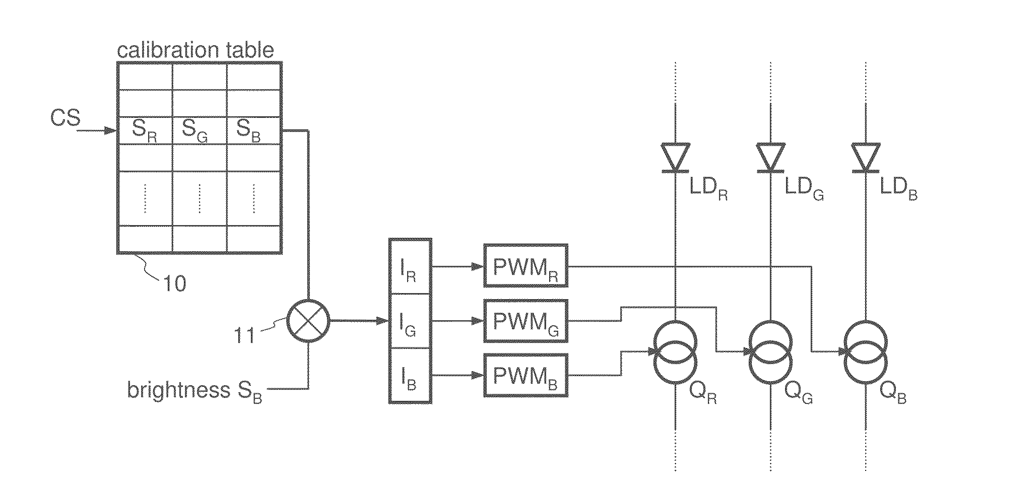
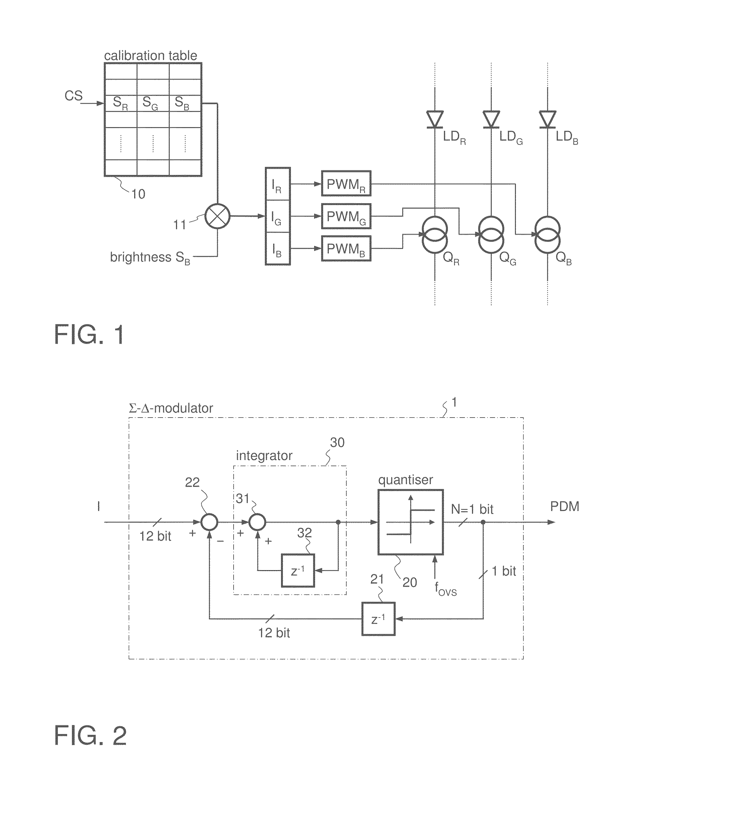
[0031]FIG. 1 illustrates a LED driver circuit for driving a LED triple, where each LED has a different color. Such LED triples can be—if adequately controlled—used for generating any color of the visible spectrum by means of additive mixture of colors. For this purpose a red LED LDR, a green LED LDG and a blue LED LDB are used. In some application a white LED is added as a fourth LED to form a LED quadruple. However, dependent on the application two different LEDs of different colors may be sufficient for color mixing. For controlling the brightness of each LED LDR, LDG, LDB each LED is connected in series to a respective controllable (in the present example switchable) current source QR, QG and QB. If, for example, yellow light is to be generated, then the load current through the red LED LDR has to be zero and the load currents through the green LED LDG and the red LED LDR have to be approximately equal, where the absolute current value depends on the desired brightness of the yel...


PUM


Abstract

A circuit arrangement includes a number of light emitting diodes emitting light of different colors arranged adjacent to each other for additive color mixing to provide a desired color. A temperature sensing circuit is configured to provide a temperature signal representing temperature(s) of the light emitting diodes. Current sources are configured to provide the light emitting diodes with respective load currents in accordance with corresponding control signals received by the current sources. First and second modulator units are configured to generate the control signals which are modulated such that a time average value of each control signal corresponds to the value of a corresponding input signal of the respective sigma-delta modulator. A calibration circuit is configured to provide the input signals dependent on a color signal defining the desired color and dependent on the temperature signal.

Description

[0001]This application claims priority to European Patent Application 11182843, which was filed Sep. 27, 2011 and is incorporated herein by reference.TECHNICAL FIELD[0002]The invention relates to the field of driver circuits for light emitting diodes (LEDs), especially for use in multi-color LED applications.BACKGROUND[0003]The brightness of light emitting diodes (LEDs) is directly dependent on the load current flowing through the diode. To vary the brightness of a LED it is known to use a controllable current source that is set to a current representing a desired brightness. In digitally controlled applications a digital-to-analog converter (DAC) may be used to set the current of the controllable current source.[0004]Since the human eye cannot resolve high frequency brightness fluctuations of approximately 100 hertz or higher, it is known to supply the LED with a pulse width modulated (PWM) current of sufficient frequency. In this case the human eye low-pass filters the resulting p...

Claims


Application Information

Patent Timeline
IPC IPC(8): H05B37/02H05B44/00
CPCH05B33/086H05B33/0872H05B33/0818G06F7/602H05B33/0824Y02B20/347H05B33/0866H05B45/24H05B45/44H05B45/37Y02B20/30H05B45/28
Inventor LOGIUDICE, ANDREA
Owner INFINEON TECH AG
Why Eureka
Try Eureka