Non-contact current and voltage sensing clamp

a non-contact, current and voltage sensing technology, applied in the field of sensors, can solve problems such as difficulty in fine work with fingers

Inactive Publication Date: 2013-03-28
IBM CORP
View PDF10 Cites 115 Cited by
  • Summary
  • Abstract
  • Description
  • Claims
  • Application Information

AI Technical Summary

Benefits of technology

[0009]The invention is embodied in a current-sensing and voltage-sensing clamp and method. A current-sensing device including a current sensor and a voltage sensor both integrated in a clamping body that can be detachably coupled to a wire. The sensor thus provides outputs indicative of the current passing through the wire as well as an electric potential on the wire, so that power can be computed.

Problems solved by technology

Installation of current sensors in a live panel requires the use of insulating gloves that make it difficult to perform fine work with the fingers.

Method used


Image

  • Non-contact current and voltage sensing clamp
  • Non-contact current and voltage sensing clamp
  • Non-contact current and voltage sensing clamp

Examples


Embodiment Construction

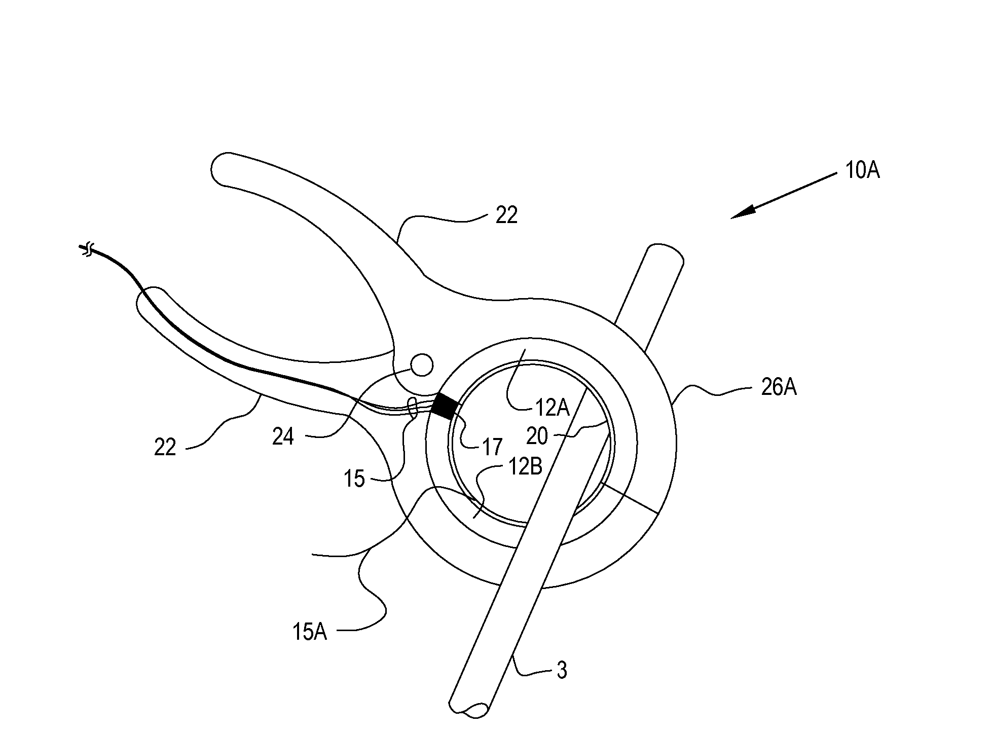
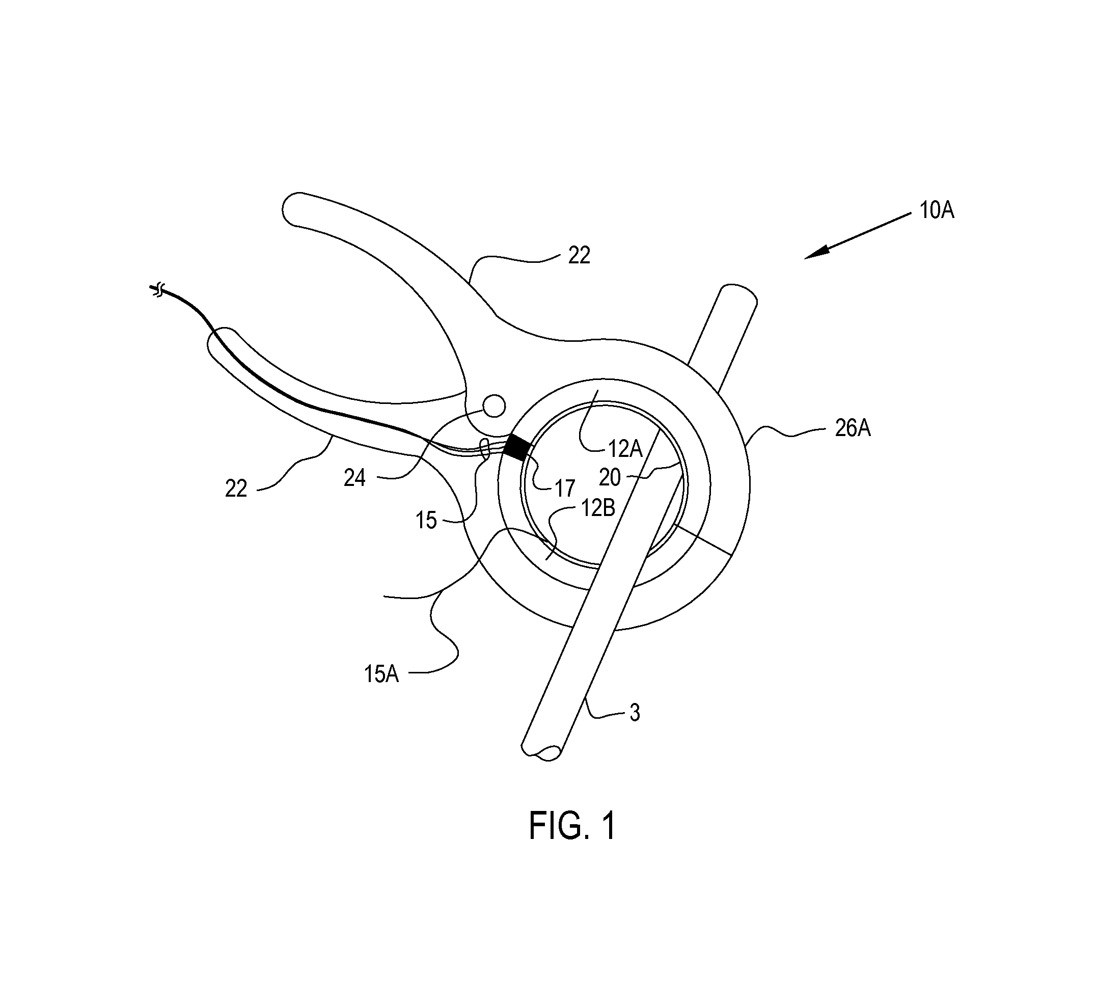
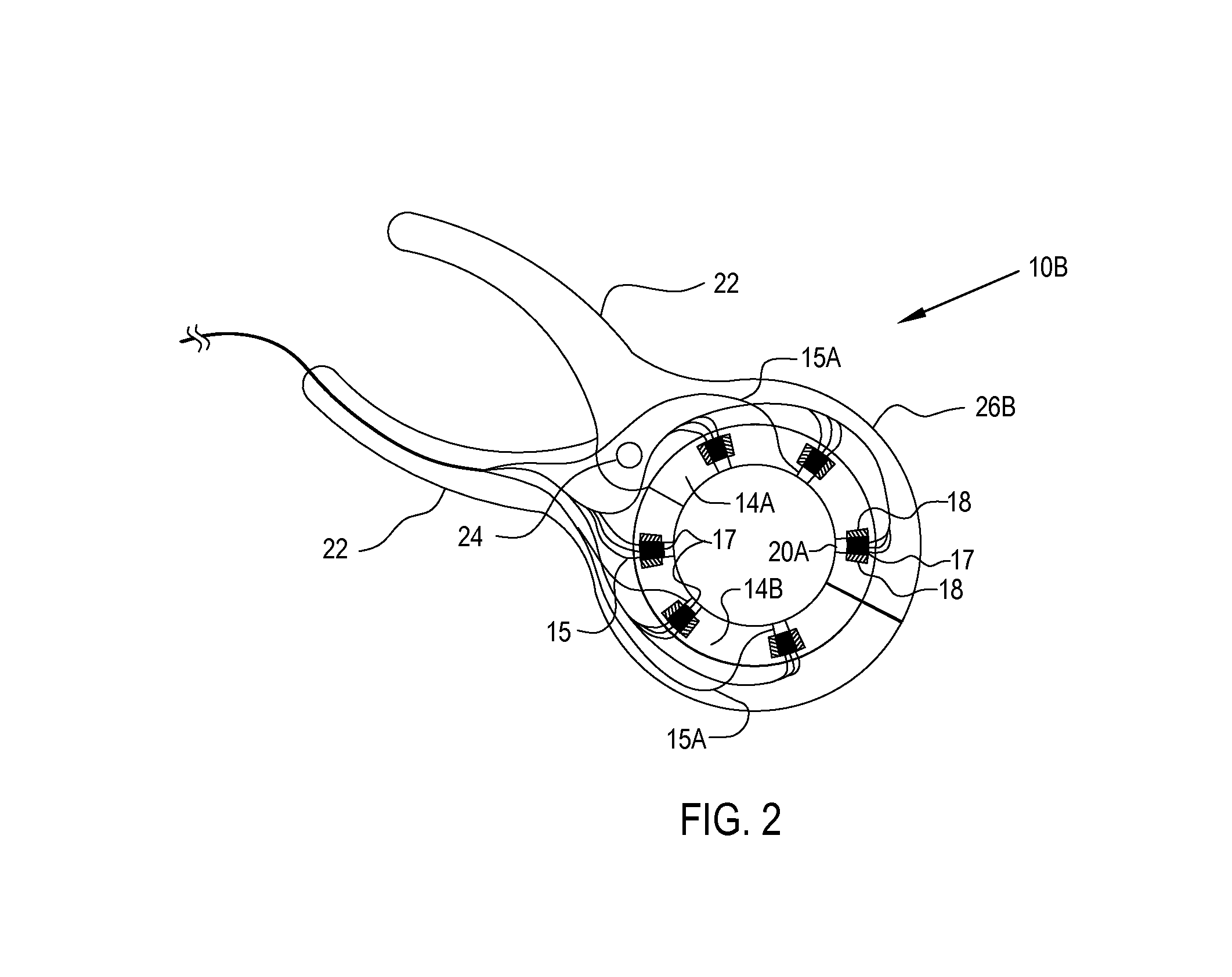
[0018]The present invention encompasses a clamping current and voltage sensor and methods of operating such sensors for providing input to power measurement systems. For example, the present invention can provide input to power monitoring equipment in computer server rooms, in which branch circuits distribute power to various electronic chassis power supplies, and in which it is beneficial to provide power usage information for the various branch circuits to power monitoring and / or system control utilities within a computer operating environment. Other applications include power monitoring for commercial and / or residential energy management. The clamping feature makes it possible to attach and detach the sensor with gloved hands, for example while measuring branch circuit power in live electrical panels.

[0019]Referring now to FIG. 1, a sensor 10A, in accordance with another embodiment of the invention is shown. Sensor 10A includes a clamp body 26A that has two handle portions 22 at ...


PUM


Abstract

A clamping current and voltage sensor provides an isolated and convenient technique for measuring current passing through a conductor such as an AC branch circuit wire, as well as providing an indication of an electrostatic potential on the wire, which can be used to indicate the phase of the voltage on the wire, and optionally a magnitude of the voltage. The device includes a body formed from two handle portions that contain the current and voltage sensors within an aperture at the distal end, which may be a ferrite cylinder with a hall effect sensor disposed in a gap along the circumference to measure current, or alternatively a winding provided through the cylinder along its axis and a capacitive plate or wire disposed adjacent to, or within, the ferrite cylinder to provide the indication of the voltage. When the handles are compressed the aperture is opened to permit insertion of a wire for measurement.

Description

[0001]The present Application is a Continuation-in-Part (CIP) of U.S. patent application Ser. No. 13 / 024,181, filed on Feb. 9, 2011 and claims priority thereto under 35 U.S.C. 120. The disclosure of the above-referenced Parent U.S. Patent Application is incorporated herein by reference.BACKGROUND OF THE INVENTION[0002]1. Field of the Invention[0003]The present invention is related to sensors providing input to power measurement systems, and more specifically to a clamping non-contact sensor that includes an electrostatic voltage sensor and an electromagnetic current sensor that can be used to detect the voltage and current at a wire of a power distribution system.[0004]2. Description of Related Art[0005]A need to measure power consumption in AC line powered systems is increasing due to a focus on energy efficiency for both commercial and residential locations. In order to provide accurate measurements, the characteristics of the load must be taken into account along with the current...

Claims


Application Information

Patent Timeline
Patent Type & Authority Applications(United States)
IPC IPC(8): G01R33/02G01R33/09G01R35/00G01R19/00
CPCG01R33/02G01R19/00G01R33/09G01R35/005G01R15/207G01R33/093G01R1/22G01R15/142G01R15/16G01R33/072
Inventor CARPENTER, GARY D.EL-ESSAWY, WAELFERREIRA, ALEXANDRE PEIXOTOKELLER, THOMAS WALTERRAJAMANI, KARTHICKRUBIO, JUAN C.SCHAPPERT, MICHAEL A.
Owner IBM CORP
Why Eureka
Try Eureka