Display device

a display device and display screen technology, applied in the field of display devices, can solve the problems of increasing the potential difference, shortening the movable distance of the shutter, and varying the brightness depending on the viewing direction

Inactive Publication Date: 2013-03-28
SNAPTRACK
View PDF1 Cites 5 Cited by
  • Summary
  • Abstract
  • Description
  • Claims
  • Application Information

AI Technical Summary

Benefits of technology

[0009]It is an object of the present invention to overcome a drawback on a

Problems solved by technology

Accordingly, there exists a drawback on a field-of-view characteristic that the brightness differs depending on the viewing direction.
Still further, the rigidity of the shutter between the first beam and the second beam is increased and hence, there aris

Method used


Image

  • Display device
  • Display device
  • Display device

Examples


Embodiment Construction

[0039]Hereinafter, an embodiment of the present invention is explained in conjunction with drawings.

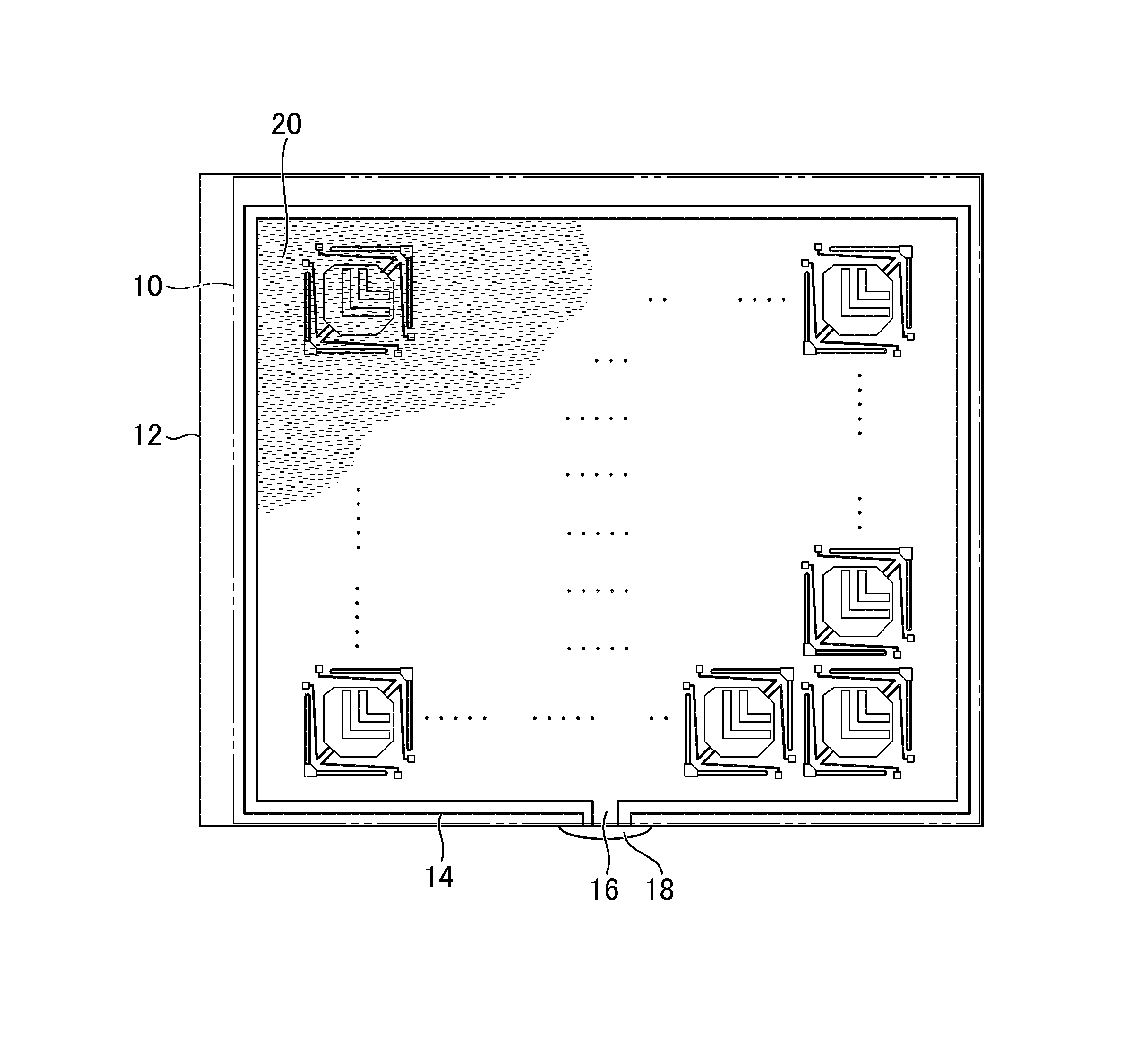
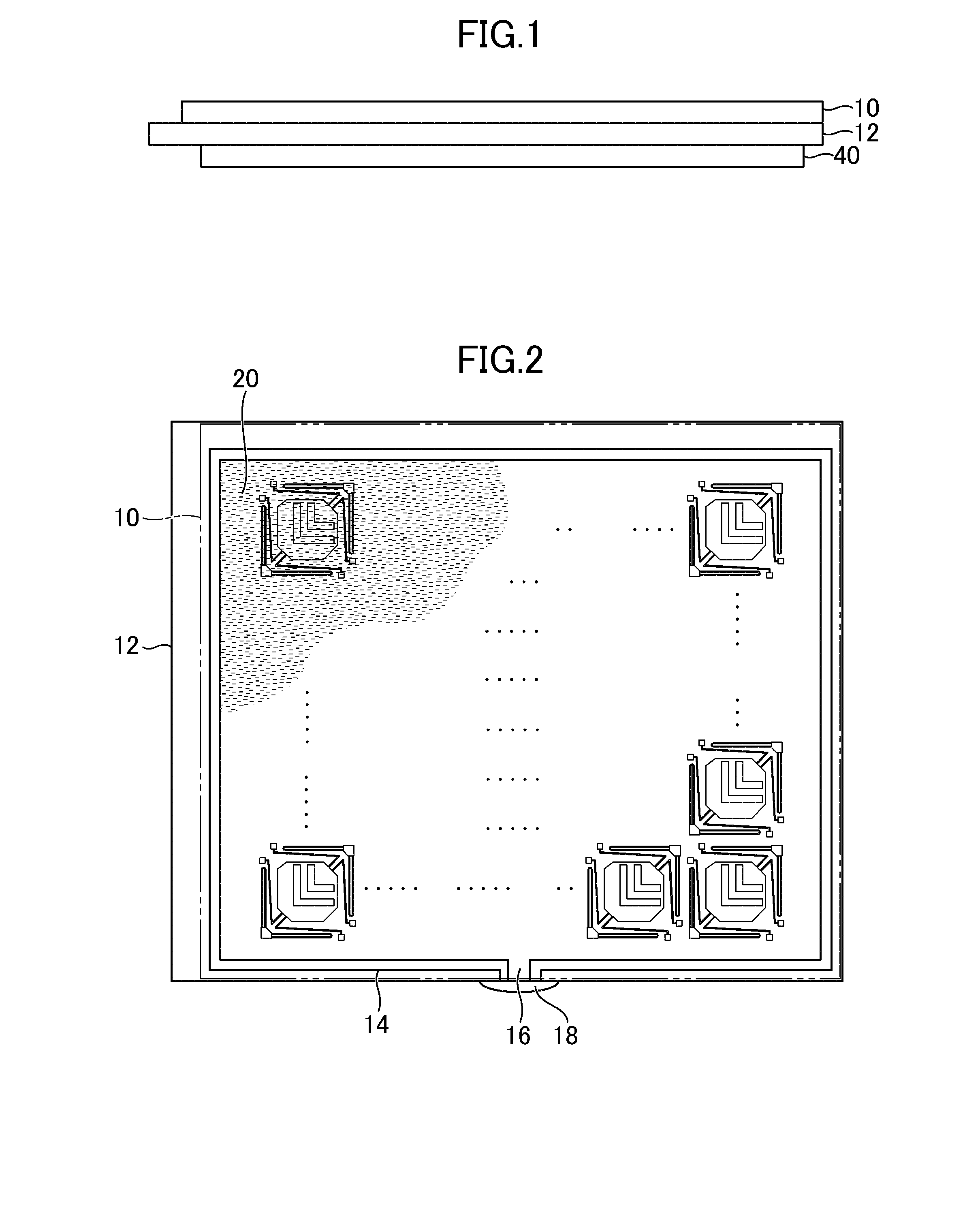
[0040]FIG. 1 is a side view schematically showing a display device according to the embodiment of the present invention. The display device includes a pair of substrates 10, 12 (for example, glass substrates) having optical transmissivity. The pair of substrates 10, 12 is arranged in an opposed manner with a gap therebetween. FIG. 2 is a plan view of the display device shown in FIG. 1. FIG. 2 shows the internal structure of the display device while indicating the upper-side substrate 10 by an imaginary line.

[0041]The pair of substrates 10, 12 is fixed to each other by a sealing material 14 shown in FIG. 2 with a gap therebetween. The sealing material 14 adheres to opposedly facing surfaces of the pair of substrates 10, 12. Further, as shown in FIG. 2, the sealing material 14 is formed in a state where the sealing material 14 surrounds a space defined between the pair of substrates 10,...


PUM


Abstract

A fixed aperture includes a first fixed slit and a second fixed slit which are arranged respectively in regions positioned on both sides with a moving line sandwiched therebetween. A drive aperture includes a first drive slit and a second drive slit which are arranged on both sides with the moving line sandwiched therebetween. The first fixed slit and the first drive slit are formed in an extending manner along a first line, and are arranged such that these slits communicate with each other when a shutter is at a position where the transmission of light is allowed. The second fixed slit and the second drive slit are formed in an extending manner along a second line which intersects with the first line, and are arranged such that these slits communicate with each other when the shutter is at a position where the transmission of light is allowed.

Description

CROSS-REFERENCE TO RELATED APPLICATION[0001]The present application claims priority from Japanese application JP2011-206777 filed on Sep. 22, 2011, the contents of which are hereby incorporated by reference into this application.BACKGROUND OF THE INVENTION[0002]1. Field of the Invention[0003]The present invention relates to a display device.[0004]2. Description of the Related Art[0005]An MEMS display (Micro Electro Mechanical System Display) is a display which is expected to take the place of a liquid crystal display (see JP 2008-197668 A). This display, unlike a liquid-crystal shutter type display which makes use of polarization, displays a tone by mechanically opening or closing a light transmitting window using a shutter unit having a shutter. To be more specific, the shutter having a drive aperture is arranged above a light blocking film where a fixed aperture is formed.[0006]Further, in the structure shown in JP 2008-197668 A, the shutter is configured to be driven by an electr...

Claims


Application Information

Patent Timeline
IPC IPC(8): G02B26/02
CPCG02B26/023G02B26/0841B81B3/0021B81B2203/051H02N1/004B81B7/02G02B26/02
Inventor NISHIZAWA, SHIGEKI
Owner SNAPTRACK
Why Eureka
Try Eureka