Autostereoscopic display

a display and autostereoscopic technology, applied in the field of autostereoscopic displays, can solve the problems of deteriorating image quality, more conspicuous grids, and significant limitations of parallax barriers, and achieve the effect of high quality

Inactive Publication Date: 2013-03-28
POPOVICH MILAN MOMCILO +1
View PDF5 Cites 36 Cited by
  • Summary
  • Abstract
  • Description
  • Claims
  • Application Information

AI Technical Summary

Benefits of technology

[0007]It is an object of the present invention to provide an autostereoscopic display th

Problems solved by technology

Parallax barriers have significant limitations.
A further problem is that increasing the number of viewpoints requires grids with wider apertures and opaque bands resulting in a more conspicuous grid and a severely reduced light transmission.
In practice, however, the image quality will deteriorate as the viewing

Method used


Image

  • Autostereoscopic display
  • Autostereoscopic display
  • Autostereoscopic display

Examples


second embodiment

[0046]FIG. 4 illustrates the invention that provides multiple viewing positions each having identical left and right eye perspective views. As shown in FIG. 4 the display is comprised of an SLM 100, a light source 200 a first light redirecting grid 2010a and a second light redirecting grid 2010b. However, in this embodiment the light redirecting grids are based on have diffusing characteristics such that light from the illuminator is scattered into a range of angles. For example, when light redirecting grid 2010a is in the ON state and light redirecting grid 2010b is in the OFF state, light is scattered along ray directions 701a to 703a and 704a to 706a towards the left eye points 31a to 33a respectively. When light redirecting grid 2010b is in the ON state and 2010a is in the OFF state, light is scattered along ray directions 701b to 703b and 704b to 706b towards the left eye points 31b to 33b respectively. The techniques for incorporating diffusing characteristics within Bragg gra...

third embodiment

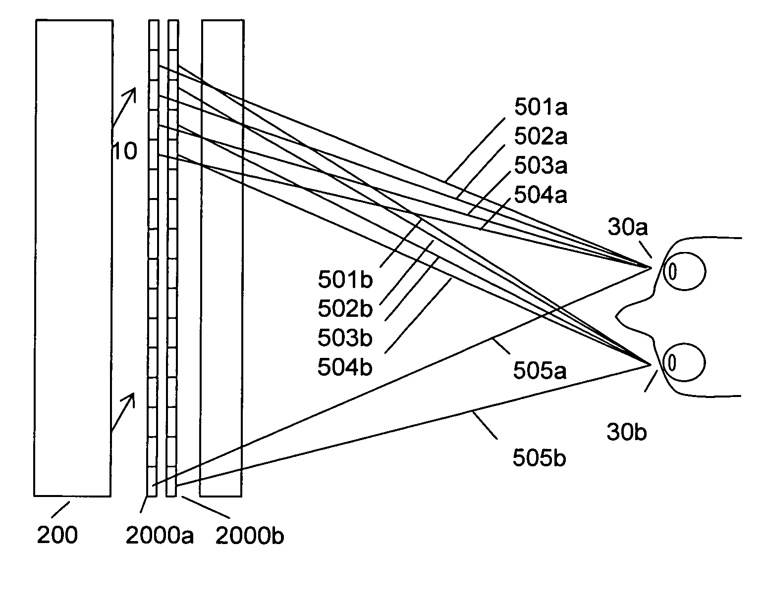
[0047]FIG. 5 illustrates the invention that provides multiple viewing positions with different left and right eye perspective views. As shown in FIG. 5 the display is comprised of an SLM 100, a light source 200 a first pair of light redirecting grids 2020a and 2020b and a second pair of light redirecting grids 2030a and 2030b. The light source provides illumination in the direction generally indicated by 10. The pair of light redirecting grids2030a and 2030b is configured to direct rays to the eye points 32a and 32b. The pair of light redirecting grids 2020a and 2020b is configured to direct rays to the eye points 31a and 31b. We first consider a first viewing position defined by eye points 31a, 31b. When the light redirecting grids 2030a is ON and the other light redirecting grids are OFF rays such as 1011b and 1012b are directed to the left eye point 31b. When the light redirecting grid 2030b is ON and the other light redirecting grids are OFF rays such as 1011a and 1012a are dire...


PUM


Abstract

An autostereoscopic display is provided comprising a Spatial Light Modulator (SLM), an illuminator, and first and second light redirecting grids. The light directing grids comprise vertical bar-shaped electrically switchable diffractive elements. The light redirecting grids direct light from the illuminator through the SLM towards left and right eye positions.

Description

REFERENCE TO EARLIER APPLICATION[0001]This application claims the priority of the U.S. Provisional Patent Application No. 61 / 202,667 filed on 25 Mar. 2009.BACKGROUND OF THE INVENTION[0002]This invention relates to autostereoscopic displays, and more particularly to an autostereoscopic display device that uses switchable holographic optical elements.[0003]Conventional stereoscopic displays provide two slightly different perspective images of the same scene. When the display is viewed using a specifically designed colored filter, or polarizing filters, the displayed scene will appear to be three-dimensional. Autostereoscopic displays achieve the same effect without any special viewing aids.[0004]An autostereoscopic display is typically comprised of an input image generator and a screen capable of producing viewer zones at a comfortable distance from the screen. The viewing zones are configured such that each eye of a viewer sees one of a stereo pair of slightly different perspective i...

Claims


Application Information

Patent Timeline
IPC IPC(8): G02F1/29G02B27/22G02B30/33
CPCG02F1/29G02B27/22G02B27/2214H04N13/00H04N13/0411G02F2203/62H04N13/0468G02F1/133512G02F1/13476G02F2001/133567H04N13/0413H04N13/312H04N13/315H04N13/366G02F1/133567G02B30/33G02B30/27
Inventor POPOVICH, MILAN MOMCILOWALDERN, JONATHAN DAVID
Owner POPOVICH MILAN MOMCILO
Why Eureka
Try Eureka