
Point-to-multipoint microwave communication

a microwave communication and multi-point technology, applied in the field of microwave communication, can solve the problem that the communication network made of point-to-point links is difficult to scal

Inactive Publication Date: 2013-03-28
SKYRIVER SPECTRUM & TECH LLC
View PDF4 Cites 177 Cited by
  • Summary
  • Abstract
  • Description
  • Claims
  • Application Information

AI Technical Summary

Benefits of technology

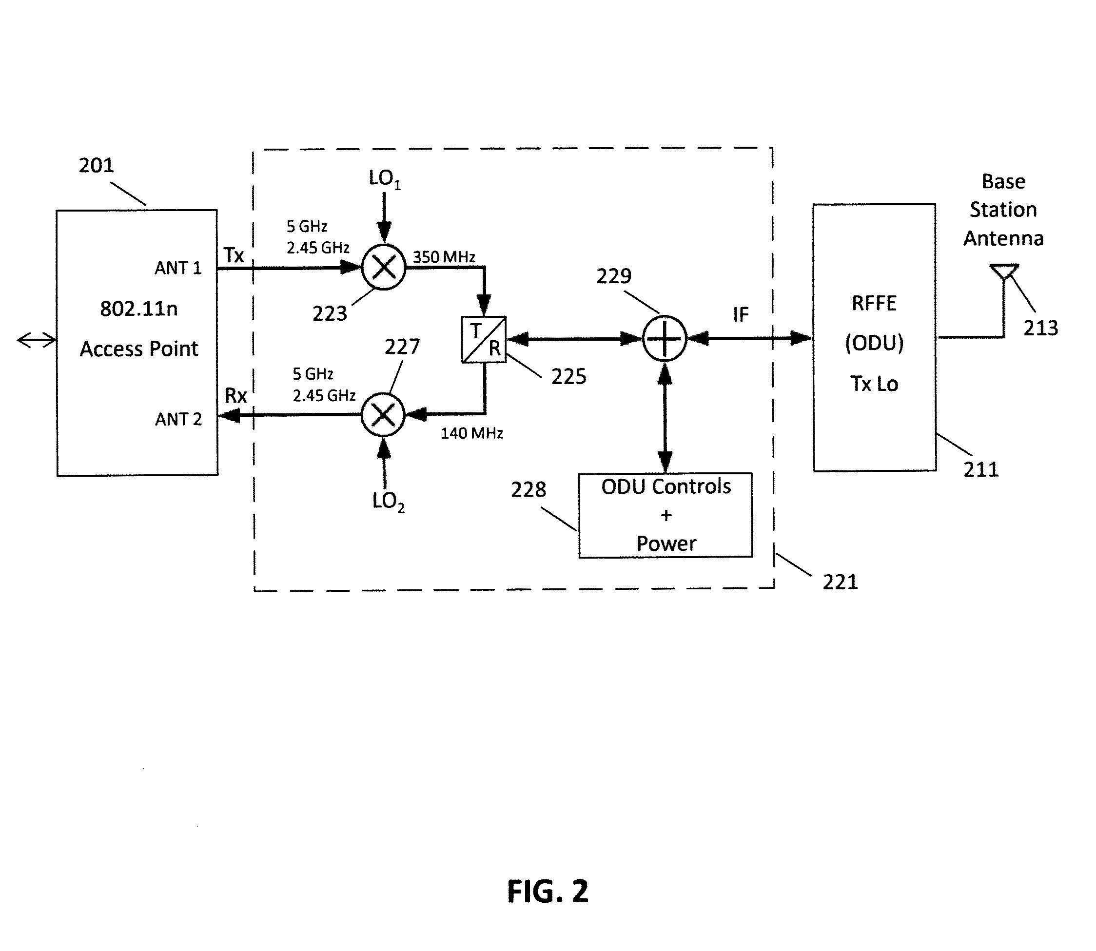
The invention relates to a communication device for a microwave communication system, which includes a wireless communication circuitry with multiple antenna ports. The device has a transmit / receive switch and a microwave radio frequency front end (RFFE) that includes circuitry to upconvert and downconvert signals. The device can transmit and receive signals at different frequencies. The technical effects of the invention include improved microwave communication capabilities, increased flexibility, and improved signal quality. The invention also provides a point-to-multipoint microwave communication system and a communication device for a microwave communication system.

Problems solved by technology

However, most systems are point-to-point, that is, they only provide communication between two locations, or points, with each location having an antenna, a radio transceiver, and other associated electronics.
A communication network made of point-to-point links is difficult to scale since adding a new location entails adding equipment both at the new location and another location, such as a base station, with which the new location will communicate over a microwave link.

Method used


Image

  • Point-to-multipoint microwave communication
  • Point-to-multipoint microwave communication
  • Point-to-multipoint microwave communication

Examples


Embodiment Construction

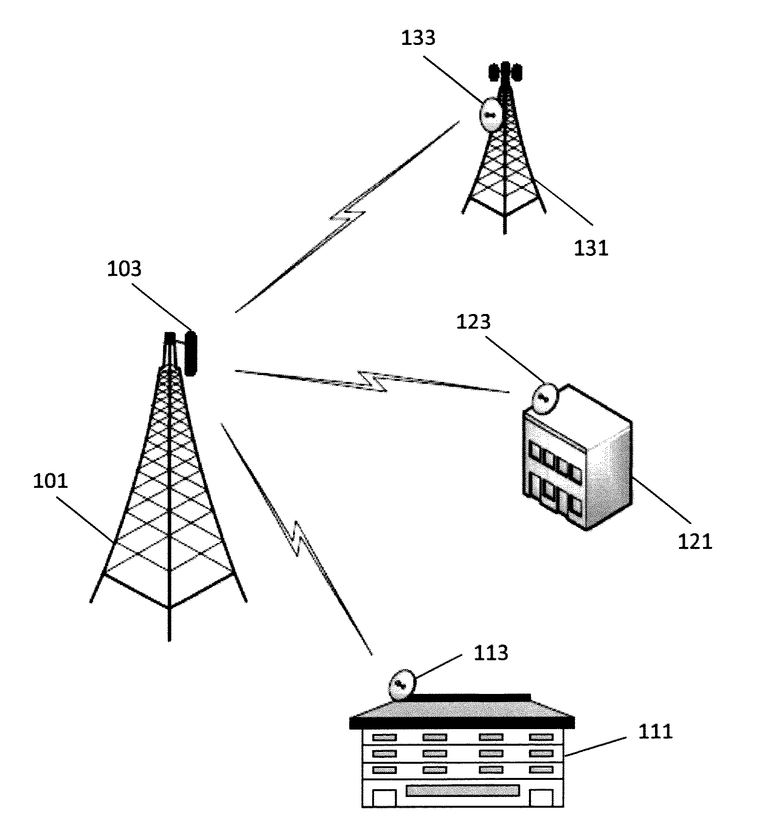
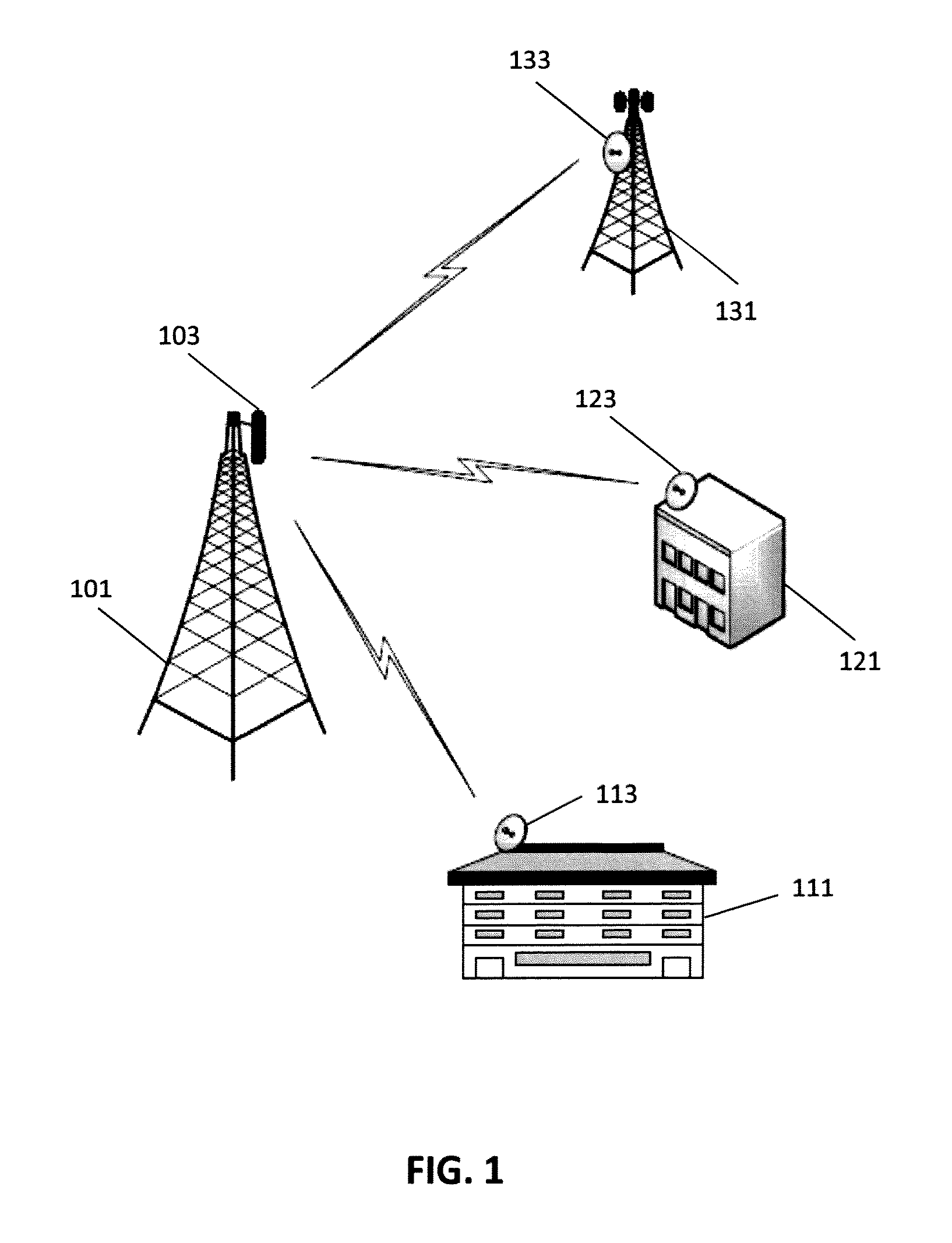
[0022]FIG. 1 is a diagram of a point-to-multipoint communication system in accordance with aspects of the invention. The communication system includes a base station 101 that includes an antenna 103 for transmitting and receiving radio signals. The antenna 103 of the base station 101, in some embodiments, is a sector antenna and may have a beamwidth of, for example, 90 degrees. The base station 101 communicates with a first subscriber station 111 via an antenna 113 approximate the first subscriber station. The base station also communicates with a second subscriber station 121 via an antenna 123 approximate the second subscriber station and a third subscriber station 131 via an antenna 133 approximate the third subscriber station. The antennas of the subscriber stations are, in some embodiments, dish antennas with narrow beamwidths. The subscriber stations may be located at various types of facilities. For example, as illustrated in FIG. 1, a subscriber station may be at a residenti...


PUM


Abstract

A microwave communication system may include subscriber stations in communication with a base station. The stations may include time duplex circuitry normally found in wireless local area networks (WLANs). Signals normally routed through antennas associated with such circuitry instead are routed through circuitry to perforin frequency conversion to and from microwave communications frequencies, for communications over microwave links between the subscriber stations and the base station. In some embodiments the wireless circuitry is configured for multiple input multiple output (MIMO) operation with one antenna port dedicated for transmission of data and one antenna port dedicated to reception of data.

Description

CROSS REFERENCE TO RELATED APPLICATIONS[0001]This application claims the benefit of U.S. Provisional Application No. 61 / 539,834, filed on Sep. 27, 2011, the disclosure of which is incorporated herein by reference.BACKGROUND OF THE INVENTION[0002]The present invention relates generally to microwave communication and, more particularly, to point-to-multipoint microwave communication.[0003]Digital microwave radio may be used to provide communication between locations. For example, mobile communication networks use microwave links to provide backhaul links from base stations. Digital microwave radio systems have progressed in both capacity and cost. However, most systems are point-to-point, that is, they only provide communication between two locations, or points, with each location having an antenna, a radio transceiver, and other associated electronics. A communication network made of point-to-point links is difficult to scale since adding a new location entails adding equipment both ...

Claims


Application Information

Patent Timeline
Patent Type & Authority Applications(United States)
IPC IPC(8): H04W4/00
CPCH04B1/0458H04B1/525H04B1/18H04B1/40H04W4/00H04L5/08H04W84/12H04W88/085H04B2001/0491H04L5/22
Inventor KHORAMI, SAEED SARIKHANI
Owner SKYRIVER SPECTRUM & TECH LLC
Learn More