Rivet setting system

a rivet and setting system technology, applied in metal-working equipment, metal-working equipment, manufacturing tools, etc., can solve the problems of large percentage of the total cost of any airplane, large number of rivets used in airplane manufacture, and difficulty in consistently setting rivets to optimal tolerance, so as to prevent inadvertent damage to the airframe

Inactive Publication Date: 2013-04-04
LEMIEUX DAVID L
View PDF2 Cites 5 Cited by
  • Summary
  • Abstract
  • Description
  • Claims
  • Application Information

AI Technical Summary

Benefits of technology

[0021]One object of preferred embodiments of the invention is to measure the formed rivet head during the rivet driving process and through a feedback control process disable or stop the rivet gun the moment the rivet head achieves the desired set tolerance. In this embodiment, an automated control process allows both operators to focus on holding their tools orthogonal to the work surface and not be concerned about under-driving or over-driving the rivet. Another object of preferred embodiments of the invention is to provide a means for communicating the stage of the rivet driving process to both rivet-gun and bucking operators by means of light, e.g., light-emitting diode (LED) indicators, with at least one LED located on or near the bucking bar and at least one LED located on or near the rivet gun. By detecting the switch states of one or more switches, the control system operates the LED indicator lights to sequentially signal the operators and thus guide them though each sequential stage of the rivet setting cycle.
[0022]It is yet another object of preferred embodiments of the invention to prevent inadvertent damage to the airframe by using a control system to disable the rivet gun when not needed and enable the rivet gun only when both the rivet-gun operator and bucker have signaled (by LED lights via a microprocessor detecting switch states) that they are ready for the rivet driving stage of a rivet setting cycle.
[0024]It is yet another object of preferred embodiments of the invention to perform data logging in computer memory of the measured rivet driven head height after the rivet has been set for Quality Assurance and Quality Control verification purposes. It is yet another object of preferred embodiments of the invention to use a proposed plunger mechanism on the bucking bar to press pieces of joined work pieces together by applying compression spring force to the work surface during the rivet setting process. Additionally, the plunger mechanism in this preferred embodiment of this invention also forms a shroud around the rivet head and thus serves to prevent the bucking tool from sliding off the formed rivet head during the rivet driving stage. This reduces the opportunity of the rivet gun hammering on a rivet this is not backed by a bucking bar and thus causing damage to the airframe or substructure work. Furthermore, the plunger mechanism also helps the bucker maintain orthogonal alignment of the bucking tool relative to the work by holding the spindles feet of the plunger flush against the work during the rivet driving cycle.
[0026]While as previously stated preferred embodiments of the invention eliminate under-driving the rivet and consequently prevents a plurality of hammering sessions; it is yet another object of preferred embodiments of the invention to maximize set rivet material strength. During the rivet driving stage, the rivet shank undergoes plastic deformation; the shank-end becomes the driven head and forms into a mushroom shape and the shank also simultaneously expands. If the gun force is set too low, then excessive rivet gun blows or impacts are required to set the rivet; this causes the rivet material to fatigue or work harden resulting in reduced material strength of the rivet and therefore reduced rivet holding strength. Ideally, rivets should be set with a minimum number of impacts but excessive rivet gun force is difficult for operators to control while simultaneously maintaining tool alignment orthogonal to the work surface. In this embodiment, therefore, the control system measures the number of impacts and the driving stage time to determine if the rivet gun impact force should be increased or decreased while also keeping the impacting force within acceptable operator-tool-control limits. The rivet setting time interval measurement begins when the rivet driving stage starts and ends when the driven head achieves optimum tolerance (when a measuring threshold has been reached). The number of impacts is preferably measured by counting the small moments in time when the bucking bar is bucked off the end of the shank immediately after receiving an impact force from the rivet gun through the rivet shank; as detected by a momentary break or switching in a circuit by a microcontroller or computer. Alternately an accelerometer or other impact detecting sensor attached to the rivet gun or bucking bar could is used to count the number of rivet-driving-stage impacts. The control system then indicates to the operator to increase or decrease the impact force or alternately automatically makes this adjustment by controlling the air pressure regulator setting for the rivet gun. Any type of communication such as LEDs, LED light bars or liquid crystal displays (LCDs) may be used to notify the rivet gun operator of recommended air-pressure regulator setting changes.
[0027]In an alternate embodiment of the invention, the operator provides computer inputs such as the rivet size being driven and the total joined sheathing material thickness into the controller's memory via any type of input device such as a keypad. This allows the controller to determine the optimal number of impacts needed for the job in order to produce the highest strength rivets and also determines the optimal tolerance threshold for the formed rivet head height 84 (where analogue sensors are employed). Those skilled in the art will appreciate that a control approach disclosed herein, coupled with real-time or near-real-time measurement of the upsetting rivet head, may also be used to set solid shank rivets at a specified location on a stress-strain curve to maximize rivet fastener strength and durability. Furthermore, with accurate and precise measurement systems coupled to real-time feedback control incorporated into the invention, achieving “ideal” or very low standard deviations (at, near or better than “six sigma”) for any desired rivet set objective is possible.

Problems solved by technology

Although the cost of installing one rivet is small, installing the great number of rivets used in airplane manufacture represents a large percentage of the total cost of any airplane.
For example, “It is often difficult to consistently set rivets to meet tolerances but it is extremely difficult to consistently set rivets to an optimal tolerance.”
If the rivet has been under-driven leaving the head height too high, additional driving is needed (although due to work hardening of the rivet material, rivet holding strength for rivets driven in repeated driving stages is often reduced).
Over-driven rivets require removal, which is a time consuming process that can often damage the work and sometimes requires using an oversized replacement rivet having a different setting tolerance.
Over-driven rivets often blemish or bend the work, sometimes causing costly rework or irreparable damage.
This communication from the bucker to the rivet gun operator to “stop riveting” is difficult to achieve because no adequate means to affect this communication, during the loud riveting process, is proposed.
Furthermore, due to reaction times of both operators and the fact that a rivet gun typically hammers at rates exceeding 20 Hertz, it is unlikely that these methods could achieve consistent desired rivet setting tolerance control.
Most importantly, if the rivet gun were not immediately stopped at the moment the bucker visually identified rivet set completion, the additional impacting forces from the rivet gun would be imparted through the rivet to the anvil face and from the set-rivet through the work to the spindle's feet resulting in the spindle's feet causing damage to the work.
Damage to the work could include bending, marring, crushing and / or scratching.
In addition to reduced strength from airframe damage or substructure damage, damage to the anodized work surfaces could also result in premature corrosion.
Due to the vibratory nature of riveting, this would be difficult to reliably observe.
Furthermore, since the spindle's feet do not rest against the work until the rivet is set, the spindle's feet are a poor tool alignment aid.
In yet another example, U.S. Pat. No. 6,011,482 by Banks et al. requires massive rail-mounted riveting equipment operating on each side of the work components being fastened together; the equipment requires costly computer numerically controlled (CNC) position control machines and extensive capital costs for the rivet driving machinery.
The reference states near line 60 that the manual “process results in rivets that were unevenly deformed, poorly seated” and near line 65 that “unfortunately, the manual process is dangerous, time consuming, expensive and often leads to extensive rework.” Also, the Banks invention only “determines the acceptability of the rivet within a component” and does not control the rivet driving process to achieve an optimal set of a driven rivet head.
While the Chitty et al. invention is used for setting blind rivets, the reference does not teach use of measured deflections of the rivet head over time and assessment of the number of impacts needed to determine optimal rivet gun pressure settings while also still maintaining settings within ranges acceptable for manual operation.

Method used


Image

  • Rivet setting system
  • Rivet setting system
  • Rivet setting system

Examples


working example

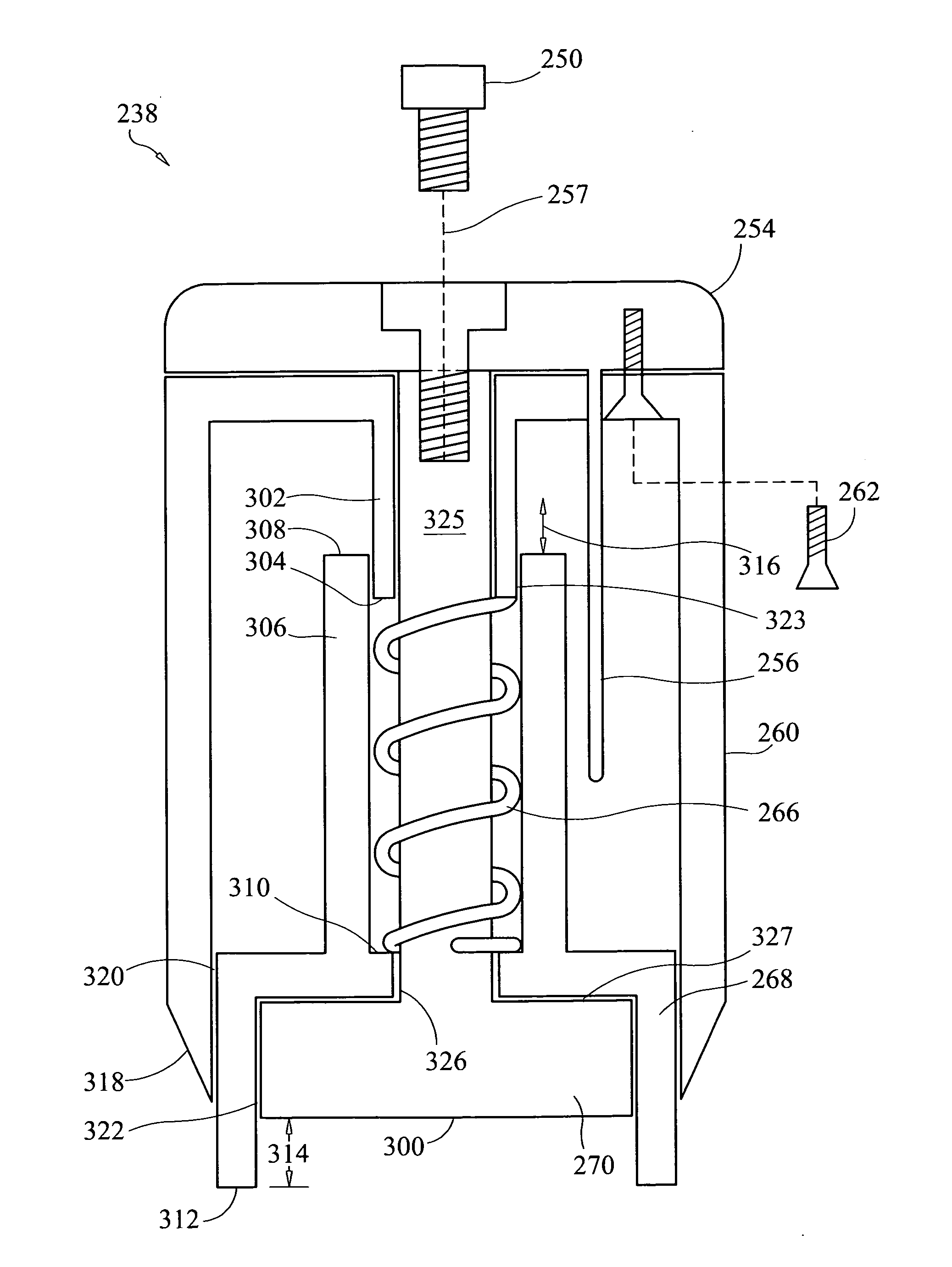
[0362]Referring to FIG. 22, a digital recording of operation of a prototype of system 100 using an oscilloscope shows bucking bar tool-to-work contact time using a preferred embodiment of bucking bar 238; the drawing represents bar 238 dynamic response to a rivet gun “hammer” cycle. Also, the recording shows clear signs of switch chatter 371 (rapid opening and closing of contacts) indicative of extreme vibration and / or shock between anvil face 300 and rivet shank end 70. Contact bounce or oscillation of movable contact upon closure of circuit was present as indicated by first contact bounce signature 373. The “switch” in this case was the make or break when the bucking bar was in contact or bounced off (not in contact) with the forming rivet head; respectively. When in contact, a voltage was detected and when not in contact, no voltage was detected. The rivet gun “hammer-blow” was indicated by first falling edge hammer signal 375. The time interval the anvil face 300 was “bucked-off...


PUM

PropertyMeasurementUnit
timeaaaaaaaaaa
timeaaaaaaaaaa
timeaaaaaaaaaa

Abstract

A system and method for rivet setting comprising a micro-adjustable bucking bar coupled to a control system that measures the rivet head during the rivet setting process and stops the rivet gun when the rivet head achieves a desired head height above the work surface. In preferred embodiments, the control system also communicates the stage of the rivet driving cycle to the operators to expedite the rivet driving process.

Description

CROSS-REFERENCE TO RELATED APPLICATIONS[0001]This is a divisional application of U.S. patent application Ser. No. 12 / 384,392, filed on Apr. 1, 2009; the disclosure of which patent application is incorporated by reference as if fully set forth herein.STATEMENT REGARDING FEDERALLY SPONSORED RESEARCH OR DEVELOPMENT[0002]Not ApplicableTHE NAMES OF THE PARTIES TO A JOINT RESEARCH AGREEMENT[0003]Not ApplicableINCORPORATION-BY-REFERENCE OF MATERIAL SUBMITTED ON A COMPACT DISC[0004]Not ApplicableBACKGROUND OF THE INVENTION[0005]This invention relates to a system and method for fastening rivets and / or using process indicators to communicate to operators the stage of each rivet during a rivet setting cycle. In particular, the invention relates to a system and method that relies on a micro-adjustable switching mechanism that is used as part of a feedback control system to achieve rivet setting tolerances by measuring in real-time or near-real-time the rivet's driven head (sometimes called the ...

Claims


Application Information

Patent Timeline
Patent Type & Authority Applications(United States)
IPC IPC(8): B21J15/10
CPCB21J15/10B21J15/02B21J15/105Y10T29/5377B21J15/36Y10T29/49943Y10T29/5307B21J15/28
Inventor LEMIEUX, DAVID L.
Owner LEMIEUX DAVID L
Why Eureka
Try Eureka