Harmonic Drive Camshaft Phaser with a Harmonic Drive Ring to Prevent Ball Cage Deflection

a technology of harmonic drive and camshaft phaser, which is applied in the direction of shafts, ball bearings, belts/chains/gearrings, etc., can solve the problems of low oil pressure, slow response of vane-type camshaft phasers at low engine speeds, and inability to meet the needs of high-speed applications, etc., to achieve the effect of limiting axial distortion

Active Publication Date: 2013-04-04
DELPHI TECH IP LTD
View PDF1 Cites 41 Cited by
  • Summary
  • Abstract
  • Description
  • Claims
  • Application Information

AI Technical Summary

Benefits of technology

[0016]Briefly described, a camshaft phaser for controllably varying the phase relationship between a crankshaft and a camshaft in an internal combustion engine is provided. The camshaft phaser includes a housing having a longitudinal axis with a harmonic gear drive unit disposed therewithin. The harmonic gear drive unit includes a circular spline and an axially adjacent dynamic spline, a flexspline disposed within the circular spline and the dynamic spline, a wave generator assembly disposed within the flexspline, and a rotational actuator connectable to the wave generator assembly such that rotation of the wave generator assembly causes relative rotation between the circular spline and the dynamic spline. The wave generator assembly includes an elliptical wave generator surrounded tightly with an inner race having an inner race axial end, an outer race surrounded tightly with the flexspline, a plurality of balls disposed between the inner race and the outer race, and a ball cage having an annular section disposed axial from the balls proximal to the inner race axial end and a plurality of ball separators extending axially from the annular section such that consecutive balls are separated by one of the ball separators. One of the circular spline and the dynamic spline is fixed to the housing in order to prevent relative rotation therebetween. A hub is rotatably disposed within the housing axially adjacent to the harmonic gear drive unit and attachable to the camshaft and fixed to the other of the circular spline and the dynamic spline in order to prevent relative rotation therebetween. A rigid support ring is fixed axially with the housing and extends axially beyond the inner race axial end toward the annular section to limit axial distortion of the annular section.

Problems solved by technology

While vane-type camshaft phasers are effective and relatively inexpensive, they do suffer from drawbacks.
First, at low engine speeds, oil pressure tends to be low, and sometimes unacceptable.
Therefore, the response of a vane-type camshaft phaser may be slow at low engine speeds.
Second, at low environmental temperatures, and especially at engine start-up, engine oil displays a relatively high viscosity and is more difficult to pump, therefore making it more difficult to quickly supply engine oil to the vane-type camshaft phaser.
Third, using engine oil to drive the vane-type camshaft phaser is parasitic on the engine oil system and can lead to requirement of a larger oil pump.
Fourth, for fast actuation, a larger engine oil pump may be necessary, resulting in additional fuel consumption by the engine.
Lastly, the total amount of phase authority provided by vane-type camshaft phasers is limited by the amount of space between adjacent vanes and lobes.
However, when a harmonic gear drive unit is used in a camshaft phaser to change the phase relationship between the crankshaft and the camshaft, stop members may be employed to limit the phase authority in order to prevent over-advancing and over-retarding which may, for example, result in undesired engine operation and engine damage due to interference of the engine valves and pistons.
Testing has shown that if the stop members are engaged with a sufficient torque applied to the wave generator assembly, the splines of the harmonic gear drive unit may be damaged by wind-up of the flex spline.
This wind-up may lead to durability and operational issues of harmonic gear drive unit 10.
Since the portion of the wave generator that extends radially outward is flush with the inner race axial end, it may not provide sufficient axial support to the ball cage.

Method used


Image

  • Harmonic Drive Camshaft Phaser with a Harmonic Drive Ring to Prevent Ball Cage Deflection
  • Harmonic Drive Camshaft Phaser with a Harmonic Drive Ring to Prevent Ball Cage Deflection
  • Harmonic Drive Camshaft Phaser with a Harmonic Drive Ring to Prevent Ball Cage Deflection

Examples


Embodiment Construction

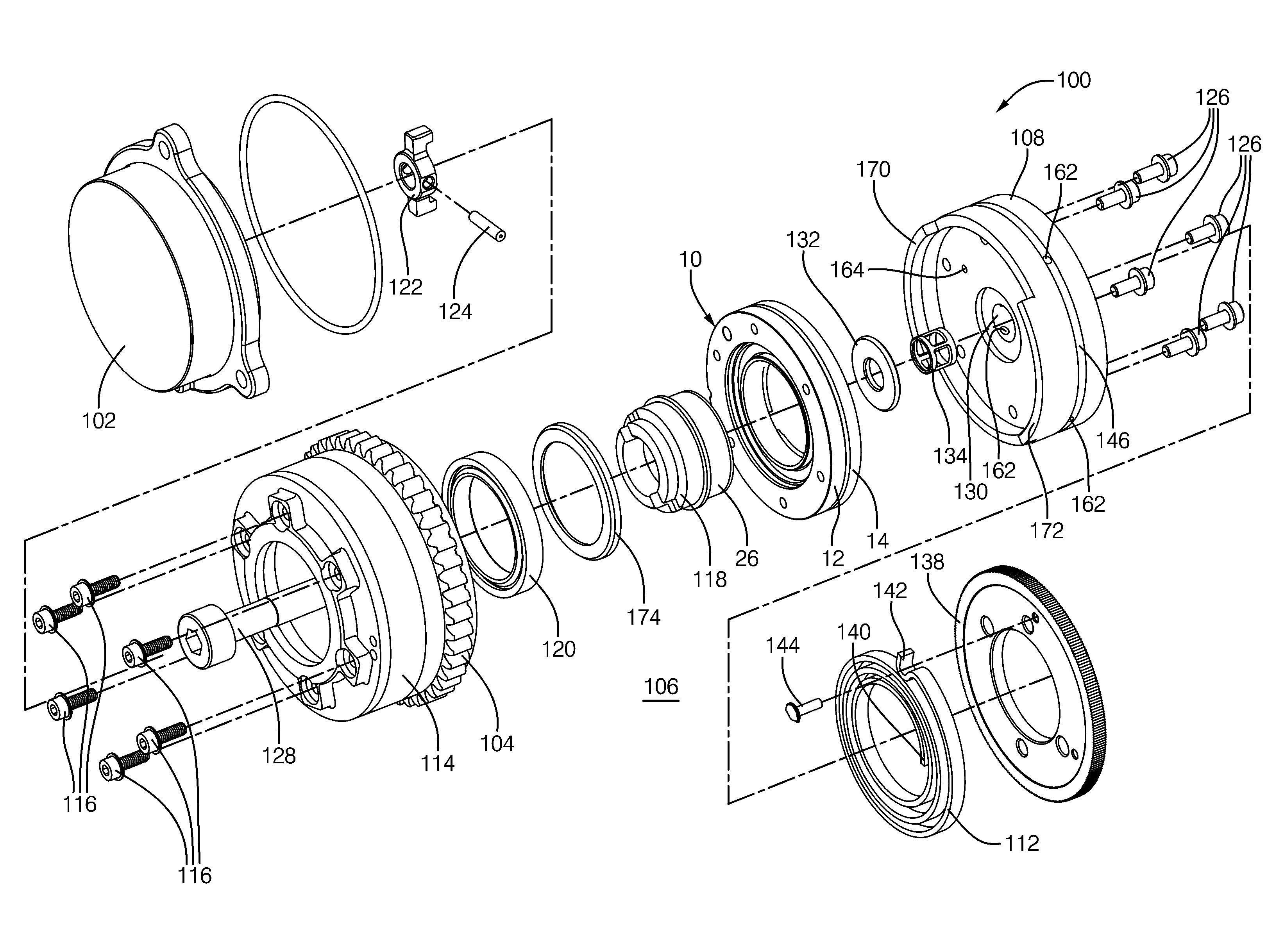
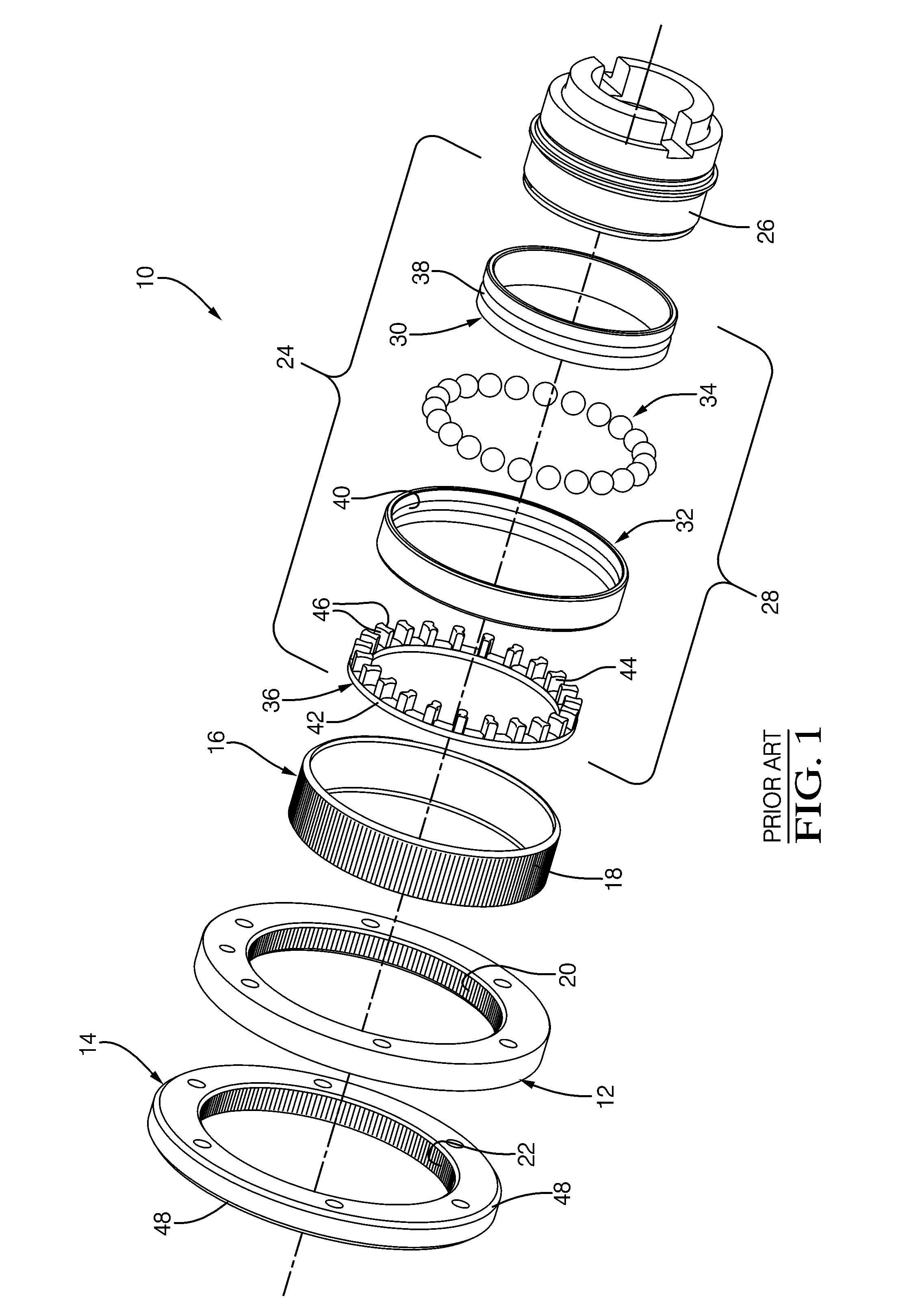
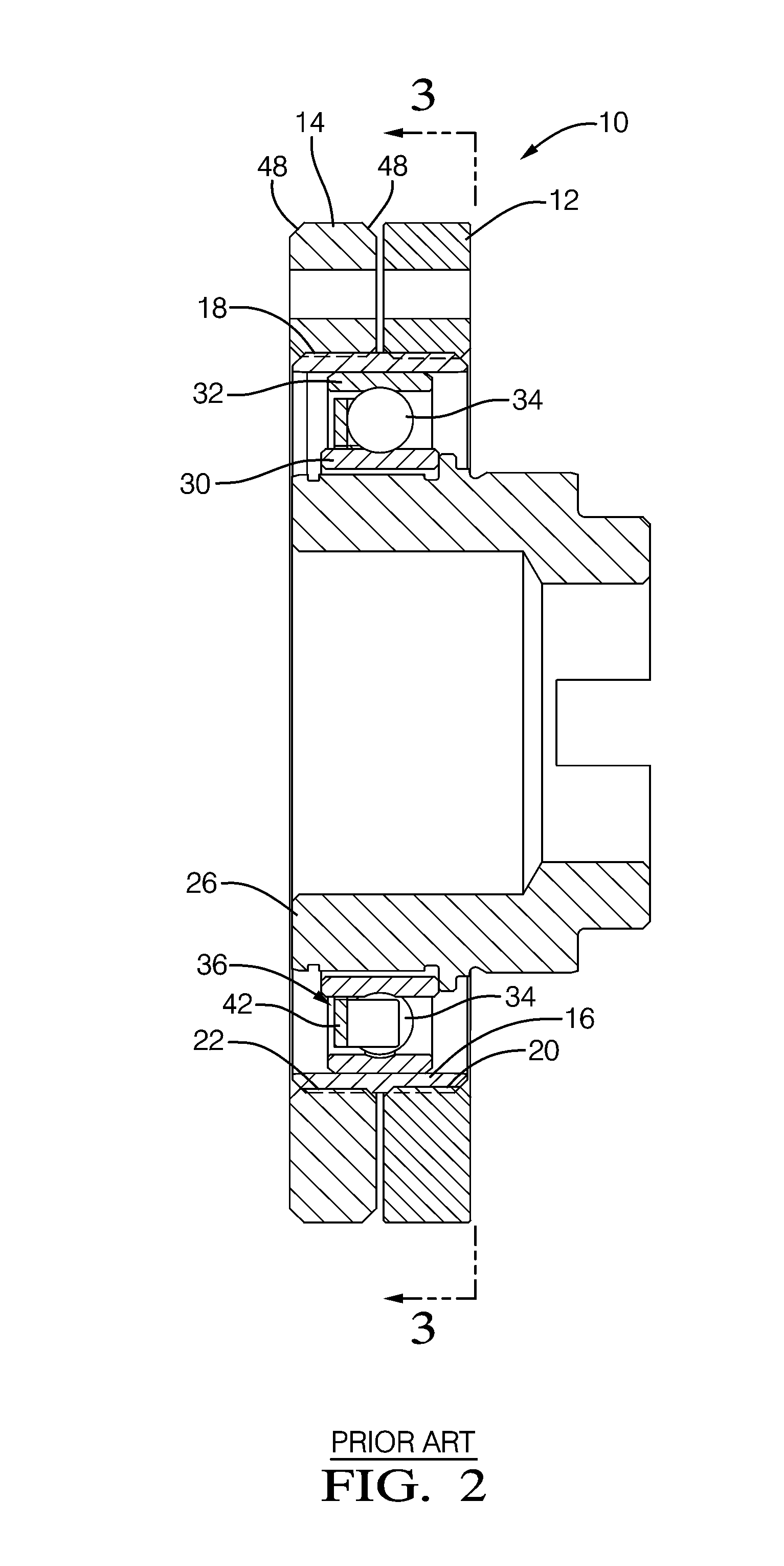
[0027]Referring to FIGS. 5 and 6, eVCP 100 in accordance with the present invention comprises flat harmonic gear drive unit 10; rotational actuator 102 that may be a hydraulic motor but is preferably a DC electric motor, operationally connected to harmonic gear drive unit 10; input sprocket 104 operationally connected to harmonic gear drive unit 10 and drivable in a fixed ratio by a crankshaft (not shown) of internal combustion engine 106; output hub 108 attached to harmonic gear drive unit 10 and mountable to an end of internal combustion engine camshaft 110; and bias spring 112 operationally disposed between output hub 108 and input sprocket 104. Electric motor 102 may be an axial-flux DC motor. Harmonic gear drive unit 10 includes the same elements and operates in the same way as described earlier.

[0028]Still referring to FIGS. 5 and 6, input sprocket 104 is rotationally fixed to a generally cup-shaped sprocket housing 114 that is fastened by bolts 116 to circular spline 12. Coup...


PUM


Abstract

A camshaft phaser includes a housing. A harmonic gear drive unit is disposed within the housing and includes a circular spline and a dynamic spline, a flexspline disposed within the circular spline and the dynamic spline, a wave generator disposed within the flexspline, and a rotational actuator connectable to the wave generator. A wave generator bearing includes an inner race with an inner race axial end, an outer race, a plurality of balls between the inner and outer races, and a ball cage. The ball cage includes an annular section disposed axial from the balls proximal to the inner race axial end and a plurality of ball separators such that consecutive balls are separated by one of the ball separators. A rigid support ring extends axially beyond the inner race axial end toward the annular section to limit axial distortion of the annular section.

Description

TECHNICAL FIELD OF INVENTION[0001]The present invention relates to an electric variable camshaft phaser (eVCP) which uses an electric motor and a harmonic gear drive unit to vary the phase relationship between a crankshaft and a camshaft in an internal combustion engine; more particularly, to an eVCP with a support ring to prevent deflection of a ball cage of the harmonic gear drive unit, and more particularly to such a support ring which extends axially into an inner race of the harmonic gear drive unit.BACKGROUND OF INVENTION[0002]Camshaft phasers for varying the timing of combustion valves in internal combustion engines are well known. A first element, known generally as a sprocket element, is driven by a chain, belt, or gearing from an engine's crankshaft. A second element, known generally as a camshaft plate, is mounted to the end of the engine's camshaft. A common type of camshaft phaser used by motor vehicle manufactures is known as a vane-type camshaft phaser. U.S. Pat. No. ...

Claims


Application Information

Patent Timeline
Patent Type & Authority Applications(United States)
IPC IPC(8): F01L1/352
CPCF01L1/344F16H49/001F16C33/414F16C19/06F01L2001/3521F16H35/008F01L2001/34483F16C2361/61F16C2360/18
Inventor DAVID, PASCALKIMUS, PIERRE
Owner DELPHI TECH IP LTD
Why Eureka
Try Eureka