Tank for construction machine

a construction machine and tank technology, applied in soil-shifting machines/dredgers, transportation and packaging, transportation of items, etc., can solve the problems of increasing residual stress, reducing internal cleanness, and long-time welding operation, and achieves excellent assembly performance, low-cost structure, and enhanced rigidity.

Active Publication Date: 2013-04-04
KOBELCO CONSTR MASCH CO LTD
View PDF2 Cites 10 Cited by
  • Summary
  • Abstract
  • Description
  • Claims
  • Application Information

AI Technical Summary

Benefits of technology

[0007]It is an object of the present invention to provide a tank to be provided in a construction machine, the tank having enhanced rigidity with a low-cost structure and an excellent assembly performance without remarked reduction in internal cleanness. The provided tank comprises a tank body, at least one first reinforcement member, and at least one second reinforcement member. The tank body includes a first wall portion, a first opposing wall portion opposing to the first wall portion in a first direction, a second wall portion lying between the first wall portion and the first opposing wall portion, and a second opposing wall portion lying between the first wall portion and the first opposing wall portion and opposing to the second wall portion in a second direction crossing the first direction. The at least one first reinforcement member is disposed across the first wall portion and the first opposing wall portion and has opposite ends welded to the first wall portion and the first opposing wall portion, respectively. The at least one second reinforcement member is disposed across the second wall portion and the second opposing wall portion while spatially crossing the at least one first reinforcement member, that is, crossing the at least one first reinforcement member with a distance in a direction perpendicular to either of the first and second directions, and has opposite ends welded to the second wall portion and the second opposing wall portion, respectively.

Problems solved by technology

In this type of a tank, there is required welding the channel member as the reinforcement member over the longitudinally full range thereof, which generates a heat involving an increase in residual stress and welding distortion.
Besides, there may occur further problems such as reduction in internal cleanness of the tank due to welding residues adhered to the inner surface of the tank, long-time welding operation, increase in the number of steps for assembling the tank, deterioration of an appearance of the tank due to embossment of welding marks remained in the side wall surface to an outer surface of the side wall, and low reinforcement effect compared with mass of the used reinforcement member.

Method used


Image

  • Tank for construction machine
  • Tank for construction machine
  • Tank for construction machine

Examples


first modified embodiment

[0048]FIGS. 7A and 7B show a tank Tf1 according to a This tank Tf1 is different from the tank Tf according to the above embodiment in shape of the first reinforcement member 51. In the following modified embodiments and other embodiments, substantially the same element or component as that in FIGS. 5 and 6 is assigned with the same reference numeral or code, and detailed description thereof will be appropriately omitted.

[0049]In the first modified embodiment, each first reinforcement member 51 has bends which incline an intermediate portion of the first reinforcement member 51 upwardly in a direction from right toward left. The right wall portion 15b has a pair of right fixing holes 22b, each of which is formed into a vertical elongate hole to allow the first reinforcement member 51 with the bends to be inserted therethrough.

[0050]The bends of the first reinforcement member 51 permits the first reinforcement member 51 to efficiently absorb deformation of the left and light wall por...

second modified embodiment

[0051]FIGS. 8A and 8B show a tank Tf2 according to a This tank Tf2 is different from respective tanks according to the above embodiment and the first modified embodiment in respective structures of the first reinforcement member 51 and the second reinforcement member 61. Specifically, in the second modified embodiment, each of the opposite ends of the upper first reinforcement member 51 and the opposite ends of the upper second reinforcement member 61 is formed with a screw hole 70 for attaching a hanging member 101 thereto, the screw hole 70 being opened outwardly in the axial direction of each of the reinforcement members 51 and 61. The hanging member 101 may be an I-bolt as shown in FIGS. 8A and 8B, or may be a hook member. The hanging members 101 thus attached to the opposite ends of the first and second reinforcement members 51 and 61 respectively enables the tank Tf2 to be stably hung up at a plurality of positions (in the shown embodiment, total four positions) by use of a h...

third modified embodiment

[0056]In the present invention, the tank body 10 is not limited to the shown rectangular box shape, but may be formed in a shape as that of a tank Tf3 shown in FIG. 9, namely, a shape having an L-shaped cross section in lateral view.

[0057]Furthermore, the present invention permits any combination among the above embodiment and the modified embodiments.

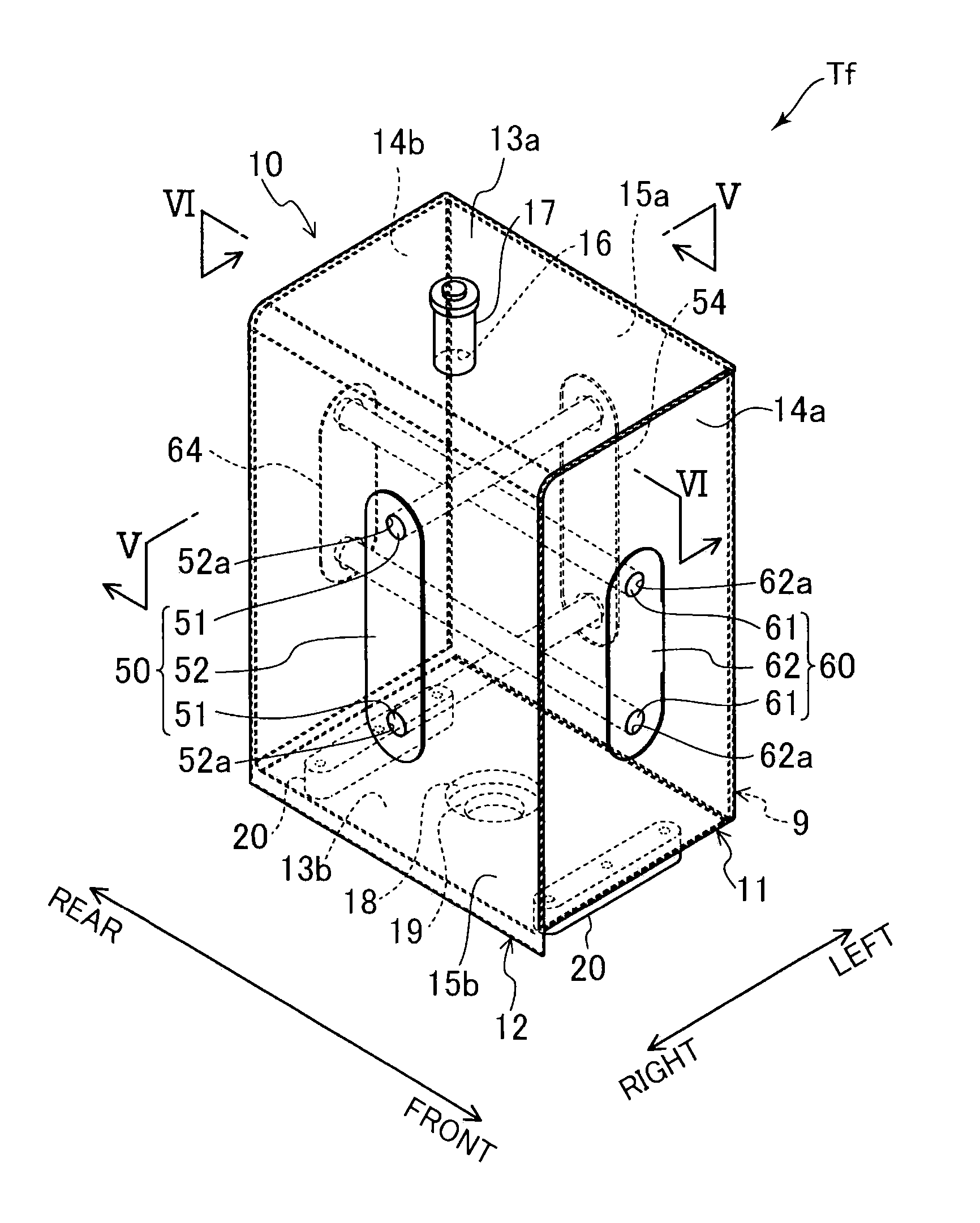
[0058]As mentioned above, the present invention provides a tank to be provided in a construction machine, the tank having enhanced rigidity with a low-cost structure and an excellent assembly performance without remarked reduction in internal cleanness. Specifically, provided is a tank which comprises a tank body, at least one first reinforcement member, and at least one second reinforcement member, the tank body including: a first wall portion; a first opposing wall portion opposing to the first wall portion in a first direction; a second wall portion lying between the first wall portion and the first opposing wall portion; and a sec...


PUM


Abstract

Provided is a tank comprising a tank body and first and second reinforcement members. The tank body includes a first wall portion, a first opposing wall portion opposing to the first wall portion in a first direction, a second wall, and a second opposing wall portion opposing to the second wall in a second direction. The first reinforcement member is disposed across the first wall portion and the first opposing wall portion, the first reinforcement member having opposite ends welded to the first wall portion and the first opposing wall portion, respectively. The second reinforcement member is disposed across the second wall and the second opposing wall portion while spatially crossing the first reinforcement member, the second reinforcement member having opposite ends welded to the second wall and the second opposing wall portion, respectively.

Description

BACKGROUND OF THE INVENTION[0001]1. Field of the Invention[0002]The present invention relates to a tank to be provided in a construction machine.[0003]2. Description of the Background Art[0004]There is conventionally known a fuel tank formed of a plurality of metal plates into a box shape, for example, as described in JP 2010-70165A. Each of the metal plates is suitably bent, and the metal plates are combined and welded to each other.[0005]This type of a fuel tank is often additionally provided with a reinforcement member to enhance strength of the tank. For example, JP 2004-189128A discloses a fuel tank having right and left side wall plates each having an inner surface and a metal-formed channel member, as a reinforcement member, welded to the inner surfaces to enhance rigidity of both of the side wall plates.[0006]In this type of a tank, there is required welding the channel member as the reinforcement member over the longitudinally full range thereof, which generates a heat invo...

Claims


Application Information

Patent Timeline
Patent Type & Authority Applications(United States)
IPC IPC(8): B60K15/03
CPCB60K15/073E02F9/0883B60K2015/03375B60K15/03B60K2015/03032
Inventor KAWAMOTO, KENJININOMIYA, CHIKARA
Owner KOBELCO CONSTR MASCH CO LTD
Why Eureka
Try Eureka