Multi-string LED driving method and system

a technology of led drive circuit and led drive circuit, which is applied in the direction of electroluminescent light sources, lighting apparatuses, light sources, etc., can solve the problems of unacceptably limiting, large input current fluctuations, complicated load conditions to be presented to the led drive circuit, etc., and achieve the effect of constant load on the drive circui

Active Publication Date: 2013-04-04
ANALOG DEVICES INC
View PDF5 Cites 18 Cited by
  • Summary
  • Abstract
  • Description
  • Claims
  • Application Information

AI Technical Summary

Benefits of technology

[0011]The present method and system requires generating PWM'd driving signals to drive respective LED strings to control their respective brightness levels, and staggering the timing of the PWM'd driving signals such that the number of LED strings driven on simultaneously varies over time by no more than one LED string. The PWM'd driving signals are generated to, for example, achieve local dimming for a display device which employs a multi-string LED backlight system; the present method enables local dimming to be achieved while maintaining a relatively constant load on the drive circuit.
[0012]Each PWM'd driving signal toggles from a first state to a second state when its LED string is to be turned on. The staggering of the timing of the PWM'd driving signals is preferably implemented by arranging the ON times of the respective driving signals such that they occur serially. The LED strings are typically driven during periodic switching cycles of fixed-duration, with the pulse-width modulation and the staggering of the driving signals occurring during each of the periodic switching cycles. Staggering the driving signals in this way has the effect of spreading the load (and on-time of each LED string) throughout each switching cycle.

Problems solved by technology

Thus, the input current suffers from large fluctuations due to the periodic and simultaneous on / off operation of the LED strings.
This technique may be effective at making the total current load nearly constant, but requires that the ON times for each LED string be identical, which may be unacceptably limiting.
However, this technique can cause a complicated load condition to be presented to the LED drive circuit.
The different currents conducted by the respective strings results in the voltage drop across each string also being different, which can make it difficult for the boost converter output voltage to provide proper headroom control for the LED strings.

Method used


Image

  • Multi-string LED driving method and system
  • Multi-string LED driving method and system
  • Multi-string LED driving method and system

Examples


Embodiment Construction

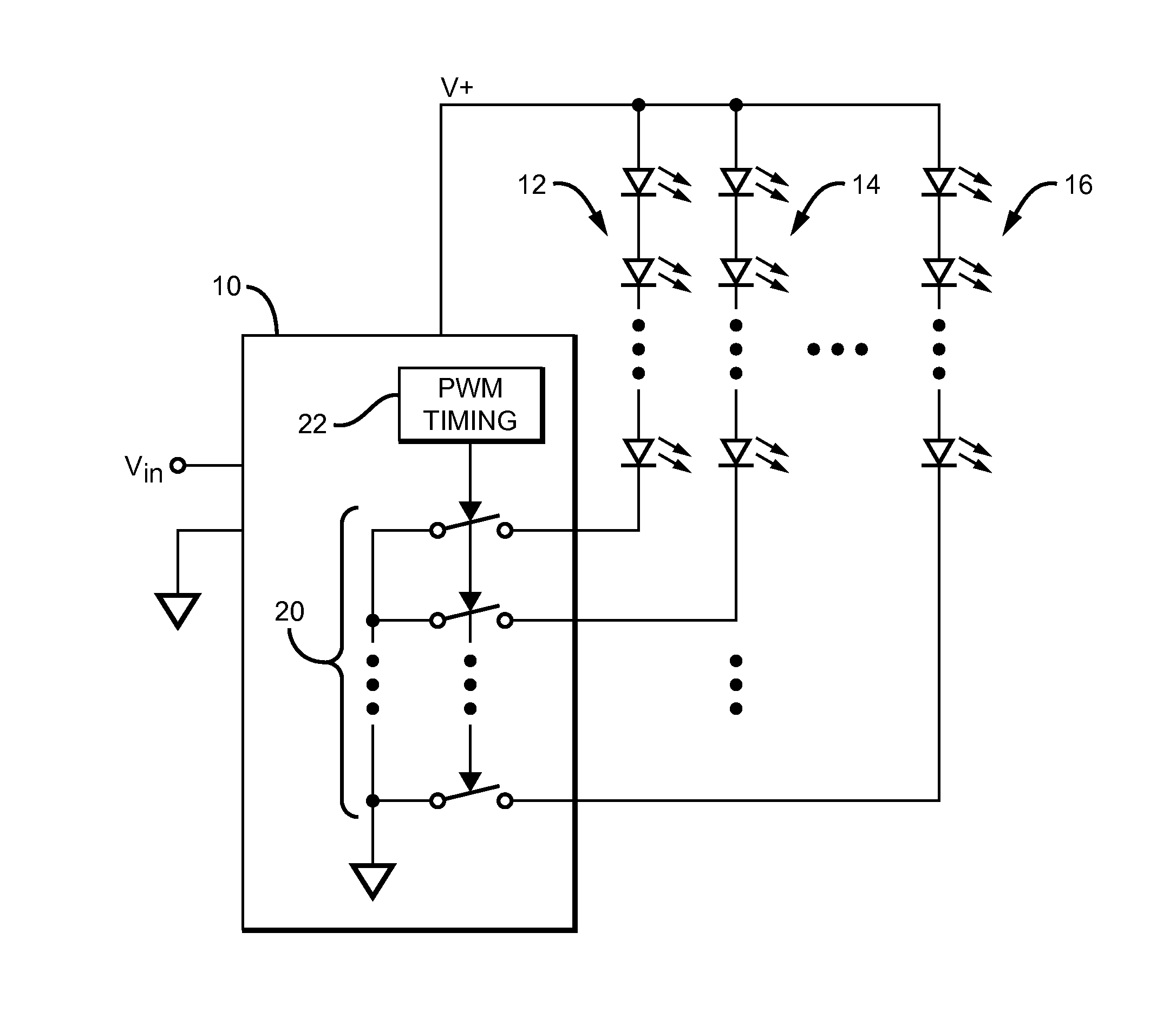
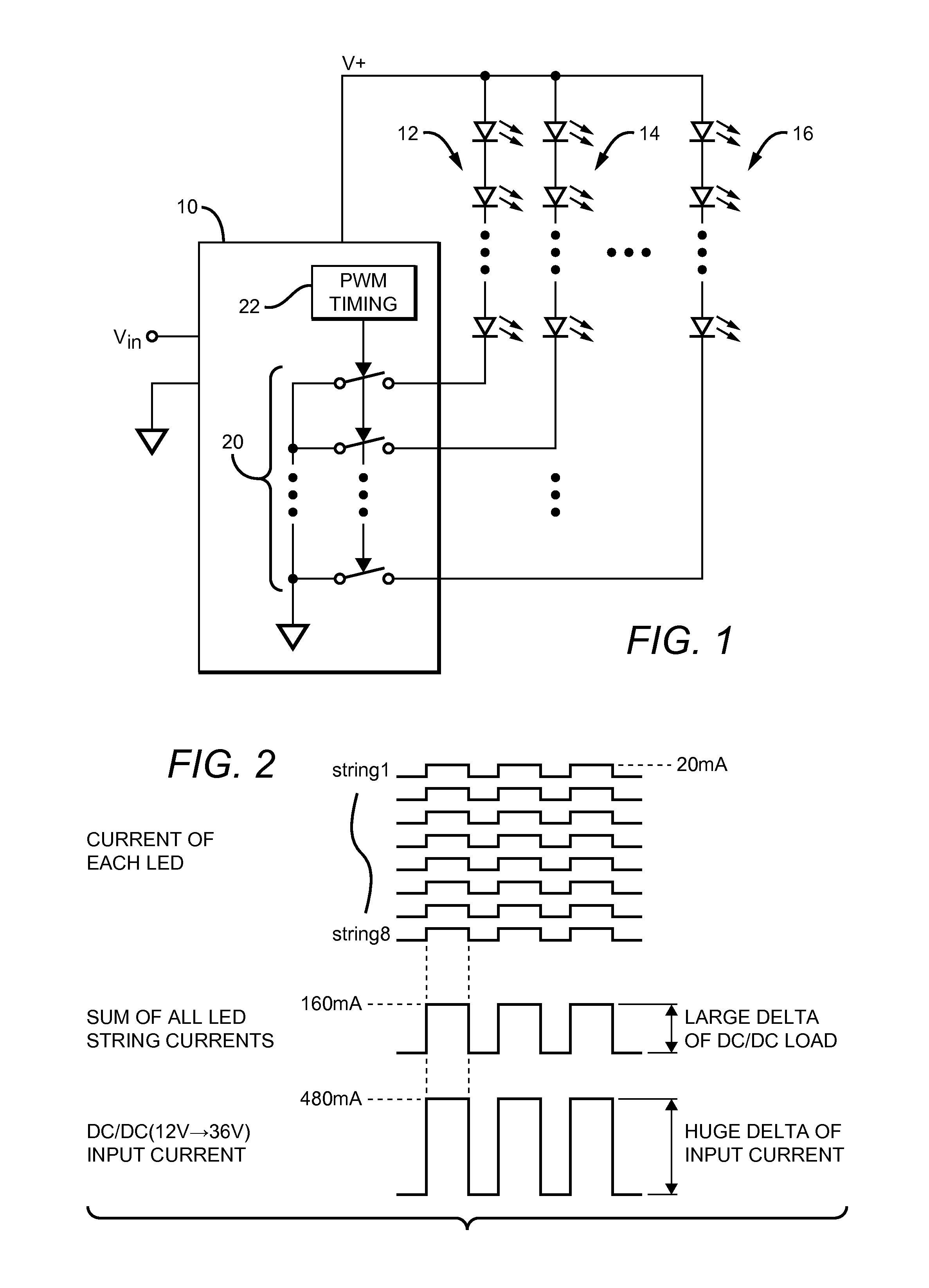
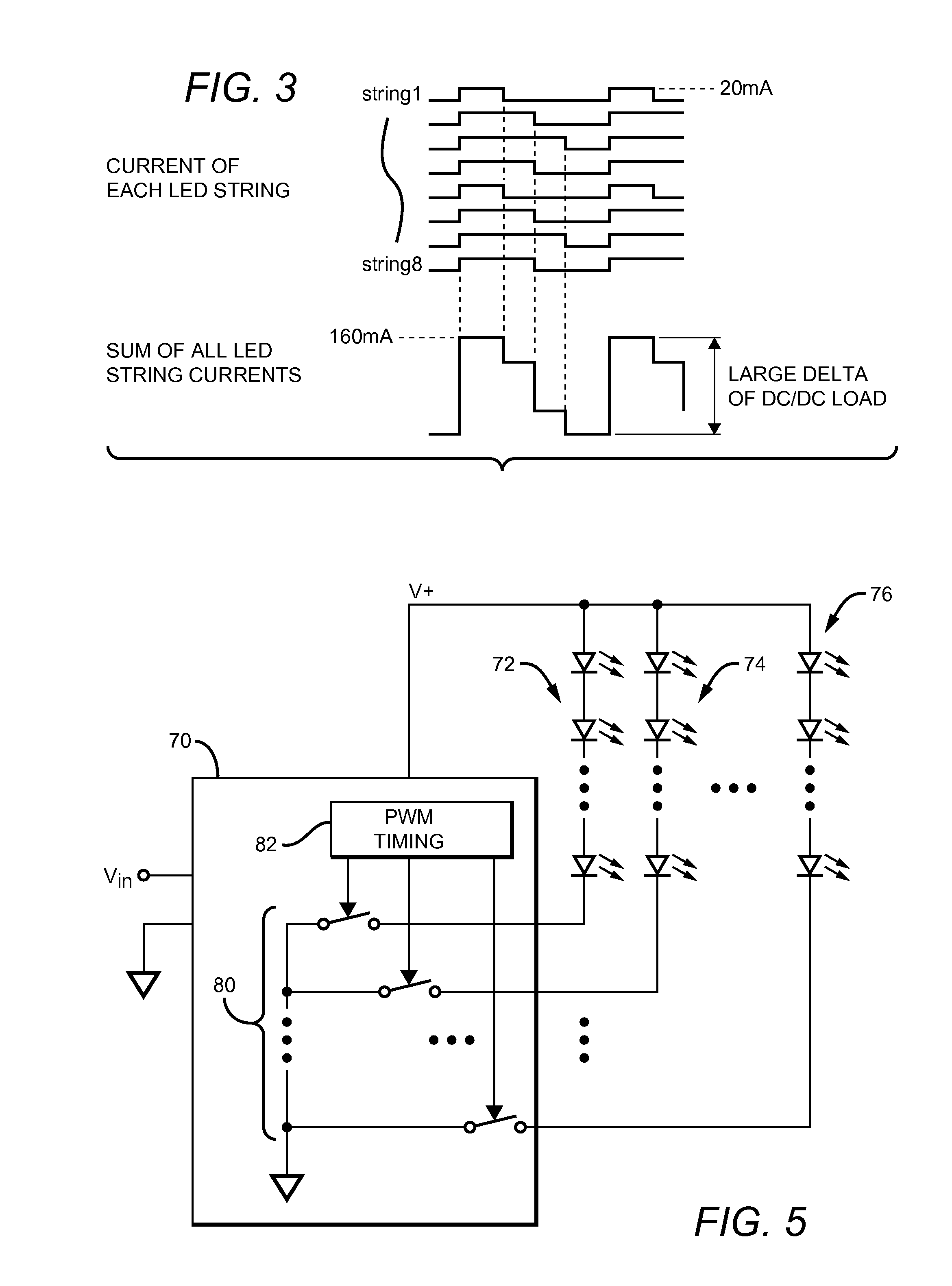
[0020]The present multi-string LED driving method is applicable to systems that pulse-width-modulate the currents conducted by multiple strings of LEDs in order to control their brightness. As before, the method requires generating PWM'd driving signals to drive respective LED strings to control their respective brightness levels. However, here, the timing of the PWM'd driving signals is staggered such that the number of LED strings driven ON simultaneously varies over time by no more than one LED string. In this way, the load imposed by the LED strings is maintained relatively constant. The present method is well-suited for use as a means of achieving ‘local dimming’ for a display device which employs a multi-string LED backlight system.

[0021]The staggering of the timing of the PWM'd driving signals preferably comprises arranging the ON times of the driving signals such that they occur serially. A timing diagram illustrating the operation of the present driving method as it might b...


PUM


Abstract

A multi-string LED driving method and system requires generating pulse-width-modulated (PWM'd) driving signals to respective LED strings to control their brightness levels, and staggering the timing of the driving signals such that the number of LED strings driven on simultaneously varies over time by no more than one LED string. The PWM'd driving signals are generated to, for example, achieve local dimming for a display device which employs a multi-string LED backlight system; the present method enables local dimming to be achieved while maintaining a relatively constant load on the drive circuit. The staggering of the timing of the PWM'd driving signals is preferably implemented by arranging the ON times of the driving signals such that they occur serially, such that the loading imposed by the LED strings is spread throughout each switching cycle.

Description

BACKGROUND OF THE INVENTION[0001]1. Field of the Invention[0002]This invention relates generally to systems for driving strings of LEDs, and more particularly to methods of facilitating ‘local dimming’ in a display device made from LED strings.[0003]2. Description of the Related Art[0004]Light-emitting diodes (LEDs) are becoming increasingly popular as a light source. In some applications, such as providing a source of backlight for a display device, many LEDs are used. The LEDs are typically connected in series, cathode-to-anode, to form an LED ‘string’, with all of the LEDs in the string driven on by applying a voltage between the first anode and the last cathode in the string. Since having a large number of LEDs in a string would necessitate a corresponding large driving voltage, the LEDs are typically arranged into a number of smaller strings, each of which can be driven on with a lower driving voltage.[0005]A simplified illustration of such a system is shown in FIG. 1. Here, an...

Claims


Application Information

Patent Timeline
Patent Type & Authority Applications(United States)
IPC IPC(8): H05B37/02H05B44/00
CPCH05B33/0827H05B45/46
Inventor SHIN, HYUNICKYOO, INSOO
Owner ANALOG DEVICES INC
Why Eureka
Try Eureka